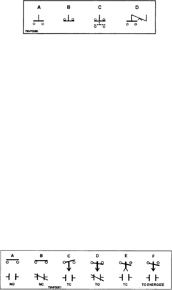
Figure 2-33.--Manually operated contacts.
In operation, this switch might be closed by a clutch in
figure 2-33.) The push button (fig. 2-33) is the simplest
a timer assembly. After the timer motor operates
form of electrical control. When the button is pushed
through a given number of revolutions, a clutch in the
down (view A), contact is made across the two circles
timer will release the contact, causing the switch to
representing wire connections. When pressure is
reopen. The timed switches may also be shown with an
released a spring (not shown) opens the contact. View
arrow that indicates whether the contact is timed to open
B shows a normally closed contact. When it is pressed,
or close. The direction of the arrow indicates what
contact at the two terminals is broken. When it is
relased, a spring-loaded feature (not shown) closes the
condition exists.
switch again. The switch in view C is designed to make
one contact and break another when it is pressed. The
LIMIT SWITCHES
upper contact is opened when the lower is closed; again,
the spring arrangement (not shown) resets the switch to
In certain applications, the ON-OFF switch does not
the position shown. The switch in view D is a
give enough to ensure safety of equipment or personnel.
maintained contact switch. When it is pressed, it hinges
A limit switch is incorporated in the circuit so that
about the center point and will stay in that position until
operating limits are not exceeded
the other part of the button is pressed.
The limit switch is installed in series with the master
ELECTRICALLY OPERATED CONTACTS
switch and the voltage supply. Any action causing the
limit switch to operate will open the supply circuit.
Schematic wiring diagrams have both push-button
One application of limit switches is in equipment
and electrically operated contacts. Two different
that moves over a track. It is possible to apply power so
methods of control contacts are shown in figure 2-34.
that operation will continue until the carriage hits an
View A shows the normally open (NO) position that
obstruction or runs off the end of the track.
closes when operated. View B shows the normally close
(NC) position that opens when energized. Views C, D,
If limit switches are installed near the end of travel,
E, and F show timer contacts. After being energized,
an arm or projection placed on the moving section will
these contacts will take some time to close or open. This
trip a lever (fig. 2-35) on the limit switch. The switch
time element is controlled by a timer motor, a dashpot,
then opens the circuit and stops the travel of the carriage.
pneumatically, or by magnetic flux. Those devices that
This type of control is a direct-acting, lever-controlled
are timed closed or open have the following indications
limit switch. Another type, an intermittent gear drive
at the lower contacts: TC (timed closed), TO (timed
limit switch, may be coupled to a motor shaft to stop
open), and TO ENERGIZE (while this contact is already
action when a definite number of shaft revolutions is
shown open, before it can be timed open, it must close).
completed.
Figure 2-34.--Electrically operated contacts.
2-30

