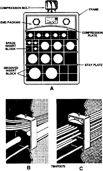
Modular insert, semicircular, grooved twin
rows of cables may be supported from an overhead in
half-blocks are matched around each cable to form a
one cable rack; two rows of cables may be supported
single block. These grooved insert blocks, which hold
from a bulkhead in one cable rack. As many as 16 rows
the cables (along with the spare insert solid blocks), fill
of cables may be supported in main cableways, in
up a cable support frame.
machinery spaces, and boiler rooms. However, not
more than one row of cables should be installed on a
During modular armored cable installation (fig.
single hanger.
2-32, view B), a sealer is applied in the grooves of each
block to seal the space between the armor and cable
Modular Cable Supports
sheath, The sealer penetrates the braid and prevents air
passage under the braid. A lubricant is used when the
Modular cable supports (fig. 2-32) are installed on
blocks are installed to allow the blocks to slide easily
a number of naval ships. The modular method saves
over each other when the y are packed and compressed
over 50 percent in cable-pulling time and labor. Groups
over the cable. Stay plates are normally inserted
of cables are passed through wide opened frames instead
between every completed row to keep the blocks
of inserted individually in stuffing tubes. The times
positioned and help distribute compression evenly
are then welded into the metal bulkheads and decks for
through the frame. When a frame has been built up, a
cable runs. The modular method of supporting
compression plate is inserted and tightened until there
electrical cables from one compartment to another is
is sufficient room to insert the end packing.
designed to be tireproof and water- and airtight.
To complete the sealing of the blocks and cables,
the two bolts in the end packing are tightened evenly
until there is a slight roll of the insert material around
the end packing metal washers. This roll indicates the
insert blocks and cables are sufficiently compressed to
form a complete seal. The compression bolt is then
backed off about one-eighth of a turn.
When removing cable from modular supports, first
tighten down the compression bolt. Tightening this bolt
pushes the compression plate further into the frame to
free the split end packing. Then, remove the end
packing by loosening the two bolts that separate the
metal washers and the end packing pieces. Back off the
compression bolt, loosening the compression plate.
Then remove this plate, permitting full access to the
insert blocks and cables.
CONTROL DEVICES
A control device, in its simplest form, is an electrical
switching device that applies voltage to or removes it
from a single load. In more complex control systems,
the initial switch may set into action other control
devices that govern motor speeds, compartment
temperatures, water depth, aiming and firing guns, or
guided missile direction. In fact, all electrical systems
and equipment are controlled in some manner by one or
more controls.
MANUALLY OPERATED CONTACTS
Manually operated switches are those familiar
electrical items that can be conveniently operated with
Figure 2-32.--Modular cable supports.
the hand. (NOTE: As you read this paragraph, look at
2-29

