making the measurements, clean the varnish from a spot
check by feeling the bearing housing whenever possible.
on a pole or tooth of the rotor. A spot should also be
Operating personnel must thoroughly familiarize
cleaned at the same relative position on each field pole
themselves with the normal operating temperature of
each bearing so they will be able to recognize any
of a dc machine. For ac machines, clean at least three
and preferably four or more spots spaced at equal
sudden or sharp changes in bearing oil temperature.
Many large generators are provided with bearing
intervals around the circumferences on the stator. Take
temperature alarm contractors, which are incorporated in
the air gap measurement between a cleaned spot on the
the ship's alarm system. The contactor is preset to
rotor and a cleaned spot on the stator, turning the rotor
provide an alarm when the bearing temperature exceeds
to bring the cleaned spot of the rotor in alignment with
a value detrimental to bearing life. You should secure
the cleaned spots on the stator. Compare these readings
the affected machinery as soon as possible if a bearing
with the tolerance stated by the manufacturer's
malfunction is indicated. A motor with overheated
instruction book.
sleeve bearings should be unloaded, impossible, without
stopping the motor. If you stop it immediately, the
Oil Rings and Bearing Surfaces
bearing may seize. The best way to limit bearing damage
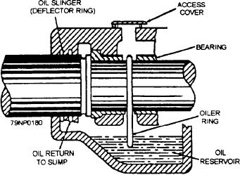
An opening is provided in the top of the bearing for
is to keep the motor running at a light load and supply
you to check the condition of the oil rings and bearing
plenty of cool, clean oil until the bearing cools down
surfaces (fig. 7-9). Periodic inspections are necessary
Because the permissible operating temperature is
to make certain that the oil ring is rotating freely when
often too high to be estimated by the sense of touch,
the machine is running and is not sticking. With the
temperature measurements should be taken to determine
machine stopped, inspect the bearing surfaces for any
whether a bearing is overheated. A thermometer
signs of pitting or scoring.
securely fastened to the bearing cover or housing will
usually give satisfactory bearing temperature
Trouble Analysis
measurements on machines not equipped with bearing
temperature measuring devices. Do not insert a
The earliest indication of sleeve bearing
thermometer into a bearing housing, as it may break
malfunction normally is an increase in the operating
and necessitate disassembly of the machinery to remove
temperature of the bearing. Thermometers are usually
broken glass and mercury.
inserted in the lubricating oil discharge line from the
bearing as a means of visually indicating the
Any unusual noise in operating machinery may also
temperature of the oil as it leaves the bearing.
indicate bearing malfunction. When a strange noise is
Thermometer readings are taken hourly on running
heard in the vicinity of operating machinery, make a
machinery by operating personnel. However, a large
thorough inspection to determine its cause. Excessive
number of bearing casualties have occurred in which no
vibration will occur in operating machinery with faulty
temperature rise was detected in thermometer readings;
bearings, and inspections should be made at frequent
in some cases, discharge oil temperature has actually
intervals to detect the problem as soon as possible.
decreased. Therefore, after checking the temperature at
the thermometer, personnel should make a follow-up
BRUSHES
Carbon brushes used in electric motors and
generators are generally constructed of one or more
plates of carbon, riding on a commutator, or collector
ring (slip ring), to provide a passage for electrical
current to an internal or external circuit. The generic
term, carbon brush, is used b y convention to denote all
brush compositions in which carbon is employed in
some proportion in one of its many structural forms,
The brushes are held in position by brush holders
mounted on studs or brackets attached to the
brush-mounting ring, or yoke. The brush holder studs,
or brackets, and brush-mounting ring comprise the
brush rigging. The brush rigging is insulated from, but
Figure 7-9.--Diagram of an oil-lubricated bearing.
7-8

