
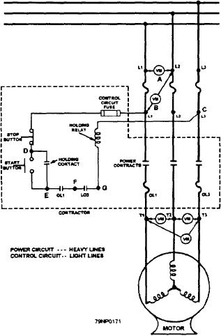
If the control circuit continuity check was of a
satisfactory value, the problem is in either the lines to
the motor, the motor, or the main contacts of the
contactor. Check the main contacts of the contactor by
manually operating the contactor and reading the
continuity across the main contacts.
If the main contacts of the contactor read good,
check the lines leading to the motor and the motor
windings themselves. You do this by measuring the
motor winding resistance between the T1 and T2 and T3
points in the controller. If there is a high or infinite
reading at this point, isolate the fault to the motor or lines
leading to the motor by reading the motor winding
resistance in the terminal connection box on the motor.
A good resistance value indicates the fault in the lines
to the motor. A high or inifinite value indicates the fault
is in the motor.
When starting a three-phase motor and the motor
fails to start and makes a loud hum, you should stop the
motor immediately by pushing the stop button. These
symptoms usually mean that one of the phases to the
motor is not energized. You can assume that the control
circuit is good since the main contactor has operated and
the maintaining contacts are holding the main operating
contactor in. Look for trouble in the power circuit
(controller line fuses, main contacts, overload heaters,
cable, and motor).
SUMMARY
Figure 6-30.--Troubleshooting a thee-phase magnetic line
starter.
In this chapter you were introduced to the
fundamentals of the various ac and dc motor and circuit
control devices to enable you to maintain, troubleshoot,
ohmmeter reads close to zero, the fault is in the contactor
and repair the equipment successfully. Almost all
coil.
equipment installed will have a manufacturer's
By maintaining the one ohmmeter lead on the L1
technical manual that should be used to adjust and repair
control circuit connection point in the controller (point
the equipment following the recommended
A) and moving the other ohmmeter lead along the
specifications. The NSTM, chapter 302, will provide
control circuit (points D then E then F) towards the first
additional information of value to you so that your
ohmmeter lead, you will localize the fault to a faulty
electrical plant will be maintained in the highest state of
readiness.
component or lead.
6-24