button, a reset-emergency run lever, or a
start-emergency run pushbutton. In each of these types,
the lever or push button must be held closed manually
during the entire emergency.
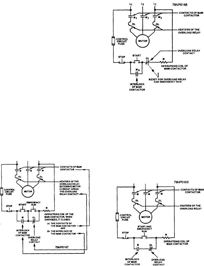
Figure 6-26 is a schematic diagram of a controller
showing a separate EMERGENCY RUN push button
with normally open contacts in parallel with the
normally closed contact of the overload relay. (NOTE:
Like all schematics, this one uses standard symbols to
show the electrical location and operating sequence of
the individual elements or devices, and it does not
indicate their relative physical location.) For
emergency run operation, the operator must hold down
this push button and press the START button to start the
motor. While the emergency run push button is
depressed, the motor cannot be stopped by opening the
overload relay contact.
A RESET-EMERGENCY RUN lever is shown in
Figure 6-27.--Schematic of controller with reset-emergency
figure 6-27. As long as the lever or rod is held down,
lever or rod.
the overload relay contact is closed. The start button
must be momentarily closed to start the motor. Figure
6-28 shows a START-EMERGENCY RUN push button.
marked start-emergency run should not be kept closed
The motor starts when the button is pushed and
for more than a second or two unless the emergency run
continues to run without overload protection as long as
operation is desired.
it is held down. For this reason, push buttons that are
Manual controllers may also be provided with an
emergency run feature. The usual means is a
start-emergency run push button or lever, which keeps
the main contactor coil energized despite the tripping
action of the overload relay mechanism.
Figure 6-28.--Schematic of controller with start-emergency
Figure 6-26.--Schematic of controller with emergency run
run push button.
push button.
6-19

