
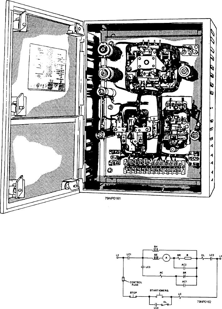
Figure 6-20.--A typical dc controller.
acceleration are shown in figure 6-21. The letters that
are in parentheses are indicated in figure 6-21. When
the start button is pressed, the path for current is from
the line terminal (L2) through the control fuse, the stop
button, the start button, and the line contactor coil (LC),
to the line terminal (L1). Current flowing through the
contactor coil causes the armature to pull in and close
the line contacts (LC1, LC2, LC3, and LC4).
When contacts LC1 and LC2 close, motor-starting
current flows through the series field (SE), the armature
(A), the series relay coil (SR), the starting resistor (R),
and the overload relay coil (OL). At the same time, the
Figure 6-21.--A dc controller with one stage of acceleration.
6-14