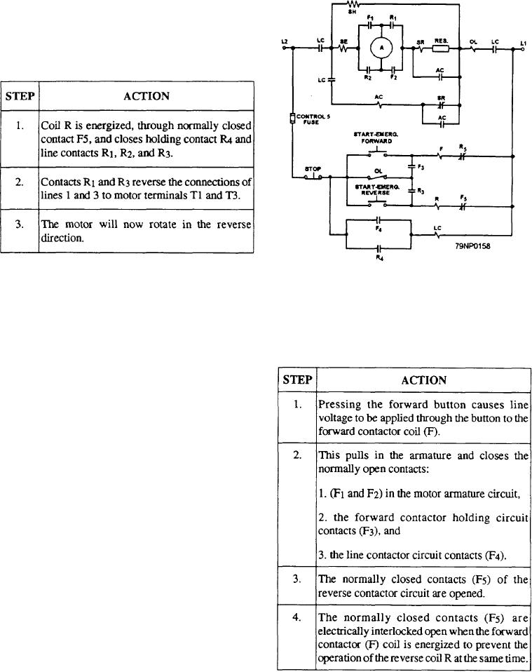
The operation of the reversing motor in the reverse
position is shown in table 6-8. After the reverse push
button is pressed (solid to dotted position):
Table 6-8--Reverse Operation of a Reversing AC Controller
The F and R contractors are both mechanically and
Figure 6-17.--Reversing dc controller.
electrically interlocked to prevent both being closed at
the same time.
The forward operation of the reversing dc controller
Momentary contact push buttons provide
is given in table 6-9.
low-voltage protection with manual restart in the
Table 6-9.--Forward Operation of a DC Controller
circuit shown in figure 6-16. If either the F or R
operating coil is de-energized, the contactor will not
reclose and start the motor when voltage is restored
unless either the forward or reverse push button is
pressed. The circuit arrangement of the normally
closed contacts F5 and R5 provides an electrical
interlock that prevents the energizing of both coils at the
same time.
DC Motors
In most applications, the direction in which a dc
motor turns is reversed by reversing the connections of
the armature with respect to the field. The reversal of
connections can be done in the motor controller by
adding two electrically and mechanically interlocked
contractors.
A dc motor reversing connection is shown in figure
6-17. Note that there are two start buttons--one marked
START-EMERG FORWARD and the other marked
START-EMERG REVERSE. These buttons serve as
master switches, and you can get the desired motor
After the line contactor is energized, acceleration is
rotation by pressing the proper switch.
accomplished in the reamer described previously.
6-12

