Low-Voltage Release (LVR)
The LVR controller (fig. 6-13) operates in basically
the same way as the LVP controller, except that its start
switch is a maintaining-type switch, such as a snap
switch. This makes the use of a maintaining circuit,
through an auxiliary contact in parallel with the start
switch, unnecessary.
If power is lost to a motor supplied by an LVR
contactor while it is operating, the motor will stop just
as if it had been turned off. Once power is restored, the
motor will restart since the start circuit was maintained
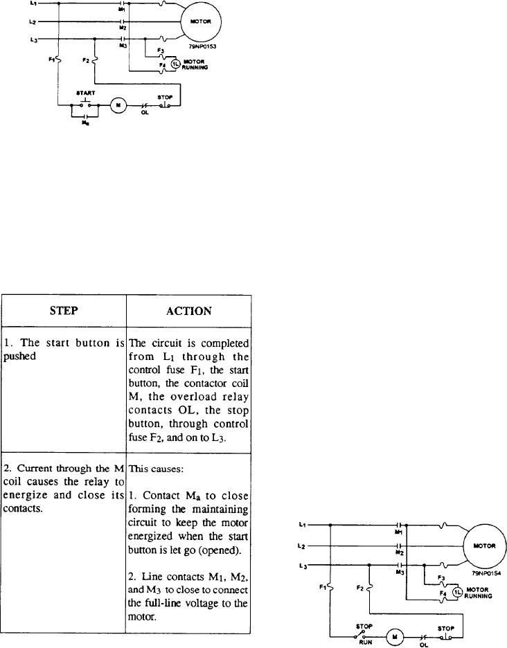
Figure 6-12.--Schematic of a simple LVP controller.
through the maintaining-type start switch. For this
reason, motors that drive loads requiring some setup by
the operator before being energized are normally
Low-Voltage Protection (LVP)
controlled by LVP controllers.
An elementary or schematic diagram of an LVP
Low-Voltage Release Effect
magnetic controller is shown in figure 6-12. Table 6-2
(LVRE)
describes the sequence of operation in starting the
motor:
The LVRE controller is actually a simple switch. It
operates in the same way as the LVR controller, except
Table 6-2.--Operation of a Simple LVP Controller
that it doesn't have a coil in its circuit to operate contacts.
The main contacts are operated by the operator
manually opening and closing the start switch. A
household light switch is an example of an LVRE
controller.
SPEED SELECTION CONTROLLERS
Both ac and dc motors maybe designed to operate
at more than one speed. In each case, controllers are
used to select the desired operating speed and protect
the motor.
The most common type of motor in the fleet is the
ac, squirrel-cage induction motor. The speed of this
The motor will continue to run until the contactor
coil is de-energized by the stop push button, failure of
Figure 6-13.--Schematic of simple LVR controller.
the line voltage, or tripping of the overload relay, OL.
6-8

