You can check the operation and contact spacing by
chosen to match the current so that the correct amount
of flux may be obtained. The blowout flux across the
manually closing the contactor (be sure the power is
arc gap is concentrated by the magnetic path provided
off). The lowest leaf of brush contact 6 should just
by the steel core in the blowout coil and by the steel pole
barely touch contact 5. If the lower leaf hits the plate
pieces extending from the core to either side of the gap.
too soon, bend the entire brush assembly upward
slightly. The contact dimensions should be measured
with the contactor in the OPEN position.
AC Contractors
Refer to the manufacturer's instruction book when
making these adjustments.
AC contractors (fig. 6-11) and control relays differ
BLOWOUT COILS.-- When a circuit carrying a
from DC contractors and control relays in three general
high current is interrupted, the collapse of the flux
areas:
linking the circuit will induce a voltage, which will
1. For heavy currents, ac contractors generally use
cause an arc. If the spacing between the open contacts
an air gap alone to quench the arc created by
is small, the arc will continue once it is started. If the
opening energized contacts while dc contractors
arc continues long enough, it will either melt the
use blowout coils.
contacts or weld them together. Magnetic blowout coils
overcome this condition by providing a magnetic field
2. AC contractors are noisier than dc contractors.
that pushes the arc away from the contact area.
Shading bands are sometimes used on ac
contactor cores to reduce noise and produce
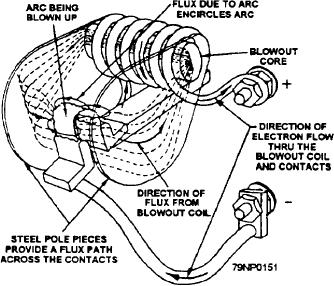
The magnetic blowout operation is shown in figure
smoother operation.
6-10. It is important that the fluxes remain in the proper
relationship. Otherwise, if the direction of the current
3. The coil of an ac contactor contains fewer turns
is changed, the direction of the blowout flux will be
of wire than a dc contactor for the same voltage;
reversed, and the arc will actually be pulled into the
therefore, it depends on inductive reactance to
space between the contacts.
produce counterelectromotive force (cemf) to
limit current flow in the coil. If an ac contactor
When the direction of electron flow and flux is as
fails to close completely, an air gap will exist in
shown in figure 6-10, the blowout force is upward. The
the magnetic circuit. This air gap reduces the
blowout effect varies with the magnitude of the current
amount of cemf produced which reduces the
and with the blowout flux. The blowout coil should be
ability of the coil to protect itself and may lead
to burnout of the coil.
The operating parts of the contactor must be kept
clean and free to operate to prevent burnout of the coils.
A regular maintenance routine of cleaning and circuit
testing according to prescribed PMS will keep
contractors free of trouble for years of operation.
CONTROLLER OPERATION
The operation of the various types of controllers is
discussed in this section of the TRAMAN.
MAGNETIC ACROSS-THE-LINE
CONTROLLERS
Across-the-line controllers are the most common
motor controllers you will encounter aboard ship. Of
Figure 6-10.--Action of a magnetic blowout coil.
the three types (LVP, LVR, and LVRE), LVPs are most
often used aboard ship to control/protect motors.
6-6

