Open-Transition Autotransformer
The open-transition compensator cuts off power to
the motor during the time (transition period) that the
motor connection is shifted from the autotransformer to
the supply line. In this short transition period, it is
possible for the motor to coast and slip out of phase with
the power supply. After the motor is connected directly
to the supply line, the resulting transition current may
be high enough to cause circuit breakers to open.
Closed-Transition Autotransformer
The closed-transition compensator keeps the motor
connected to the supply line during the entire transition
period. In this method, the motor cannot slip out of
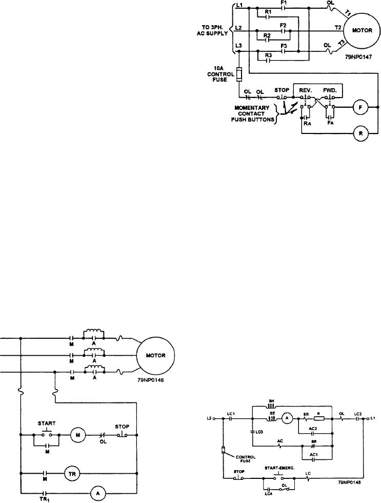
Figure 6-6.--Schematic of a reversing ac controller.
phase and no high transition current can develop.
REACTOR CONTROLLER
by interchanging any two of the three lines providing
power to the motor. Look at figure 6-6. Standard
A reactor controller (fig. 6-5) inserts a reactor in the
practice when reversing three-phase ac motors is to
primary circuit of an ac motor during starts and later
interchange L1 and L3.
short-circuits the reactor to apply line voltage to the
motor. The reactor controller is not widely used for
DC motors are reversed by reversing the
starting large ac motors. It is smaller than the
connections to the armature. DC controllers accomplish
closed-transition compensator and does not have the
this through the use of drum switches.
high transition currents that develop in the
VARIABLE-SPEED CONTROLLER
open-transition compensator.
A motor static variable-speed controller consists of
REVERSING CONTROLLER
solid-state and other devices that regulate motor speeds
Reversing controllers act to change line connections
in indefinite increments through a predetermined range.
to the motors under control causing the direction of
Speed is controlled by either manual adjustment or
rotation to reverse. Three-phase ac motors are reversed
actuation of a sensing device that converts a system
parameter, such as temperature, into an electric signal.
This signal sets the motor speed automatically.
DC RESISTOR CONTROLLER
In a dc resistor motor controller (fig. 6-7), a resistor
in series with the armature circuit of the dc motor limits
the amount of current during starts, thereby preventing
Figure 6-7.--Schematic of a dc resistor controller with one
Figure 6-5.--Schematic of a reactor controller.
stage of acceleration.
6-3

