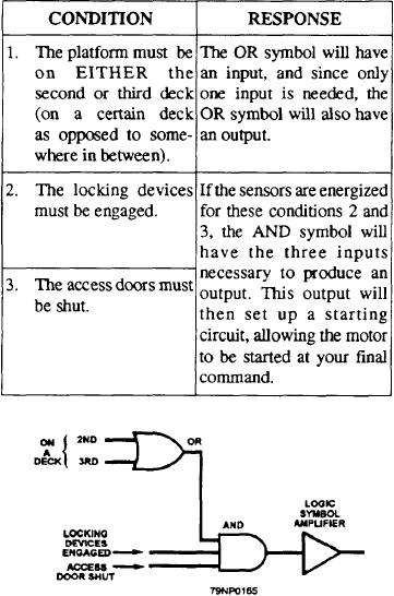
section describes the various means of protection
figure 6-24. Three conditions (detected by electronic
available to motors by the controller used.
sensors usually associated with the driven component)
must be met before the elevator can be safely moved.
VOLTAGE PROTECTION
A drop in voltage supplied to a motor under load
could severely damage the motor windings. If allowed
to remain on the line, the current through the windings
could become excessive and cause damage to the motor.
Low voltage type controllers (LVP, LVR, and
LVRE) are designed to remove a motor from the line
upon a drop in line voltage. Once line voltage drops to
a predetermined level, the main contactor coil (or an
undervoltage coil controlling it) will dropout. This will
function to open its contacts and remove the motor from
the line.
Once line voltage has been restored, the motor may
be restarted normally.
OVERLOAD PROTECTION
Nearly all shipboard motor controllers provide
overload protection when motor current is excessive.
This protection is provided by either thermal or
magnetic overload relays, which disconnect the motor
from its power supply, thereby preventing the motor
from overheating.
Overload relays in magnetic controllers have a
normally closed contact that is opened by a mechanical
device, which is tripped by an overload current. The
opening of the overload relay contact de-energizes the
circuit through the operating coil of the main contactor,
Figure 6-24.--Basic logic circuit.
causing the main contactor to open, and secures power
The advantages of these electronic switches over
to the motor.
mechanical switches are low power consumption, no
Overload relays for naval shipboard use can usually
moving parts, less maintenance, quicker response, and
be adjusted to trip at the correct current to protect the
less space requirements. A typical static logic panel
motor. If the rated tripping current of the relay does not
found aboard ship is shown in figure 6-25.
fit the motor it is intended to protect, it can be reset after
Although there are more logic symbols than AND
tripping so the motor can be operated again with
and OR, they all incorporate solid-state devices. For
overload protection. Some controllers feature an
more information, see NEETS, Module 7, NAVEDTRA
emergent y-run button that enables the motor to be run
B72-07-00-92, Introduction to Solid-State Devices and
without overload protection during an emergency.
Power Supplies.
Thermal Overload Relays
PROTECTIVE FEATURES
The thermal overload relay has a heat-sensitive
element and an overload heater that is connected in
As its name implies, the primary purpose of motor
series with the motor load circuit. When the motor
controllers is to control the operation of the motor
current is excessive, heat from the heater causes the
connected. In accomplishing this function, it is
heat-sensitive element to open the overload relay
imperative that the controller be able to operate as well
contact. This action breaks the circuit through the
as protect the motor being controlled. The following
6-16

