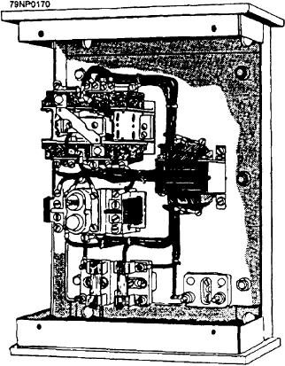
controller circuit must be checked for possible fault. As
the overload relay reset push button. Then attempt to
you read this section, refer to figures 6-29 and 6-30.
start the motor. If the motor operation is restored, no
further checks are required. However, if you hear the
Remove the controller line fuses or verify that the
controller contacts close but the motor fails to start, then
fuses are removed. Danger tag the controller line fuses
check the motor circuit continuity. If the main contacts
that have been removed and taking the applicable
don't close, then check the control circuit for continuity.
electrical safety precautions according to NSTM,
An example of troubleshooting a motor-controller
chapter 300, check the controller de-energized.
electrical system is given in a sequence of steps that may
be used in locating a fault:
Using an ohmmeter, check the continuity of the
control circuit between the L1 and the L3 connection
1. Symptom recognition-recognize the normal
points (point A and B of fig. 6-30) in the controller while
operation of the equipment
holding the start button in the START position. If the
2. Symptom elaboration-recognize/observe the
control circuit is good, the ohmmeter should read a
faulty operation of the equipment
resistance equivalent to the resistance value of the
3. Listing of probable faulty functions-develop a
contactor coil. Depending on the size of the coil, this
list of possible causes for the malfunction
value could be anywhere from a couple hundred ohms
to a couple thousand ohms. If the ohmmeter reading is
4. Localizing the fault-determine the most likely
infinite, the problem is in the control circuit.
areas of failure to create the symptoms noted
5. Localizing the trouble to the circuit-using test
To isolate the fault in the control circuit, leave one
equipment, isolate the malfunction down to the
of the ohmmeter leads on the L1 control circuit
most likely component(s)
connection point (point A) and move the other lead of
the ohmmeter to the other side of the contactor coil in
6. Failure analysis-verify the component(s) is/are
the controller (point C). If while holding the start button
faulty
in the ON position the ohmmeter reads infinite, the fault
Let's start by analyzing the power circuit.
is between point A and C in the control circuit. If the
POWER CIRCUIT ANALYSIS
When no visual signs of failure can be located and
an electrical failure is indicated in the power circuit, you
must first check to see if power is available and the line
fuses are good. See if the supply source is available by
checking that the feeder breaker is shut and other
equipment receiving power from that breaker is
operational. Only under extremely rare situation would
there be a break in the cabling going to the line fuses.
Taking applicable electrical safety precautions
according to NSTM, Chapter 300, remove the line fuses
and check the continuity of the fuses. While removing
the fuses, check for lose fuse clips which could give a
faulty connection to the line fuse. If power is available
and the line fuses are good, then the problem is in either
the control circuit, the motor line leads, or the motor
itself.
CONTROL CIRCUIT ANALYSIS
Taking applicable electrical safety precautions
according to NSTM, chapter 300, remove the control
fuse and check the fuse continuity. If the fuse is bad,
replace the fuse with a fuse of proper size and rating and
Figure 6-29.--Typical three-phase controller.
retest the controller. If the control fuse is good, the
6-23

