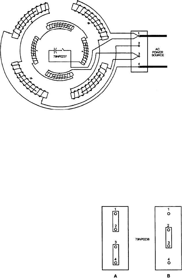
Figure 7-70.--Single-phase, capacitor-start, inductor-run motor diagram.
1. Inspect the motor for defects such as cracked end
SINGLE-PHASE (SPLIT-PHASE) AC
plates, a bent shaft, a broken or burned winding.
MOTOR REPAIR
2. Check the motor forbearing troubles.
There are many applications for single-phase
motors in the Navy. They are used in interior
3. Test the motor for grounds, opens, and shorts
communications equipment, refrigerators, fans,
(see armature and three-phase stator sections).
drinking fountains, portable blowers, portable tools, and
If rewinding is required, record the necessary data
many other applications. Single-phase motors are
on a single-phase motor data card (fig. 7-69).
considerably cheaper in fractional horsepower sizes; but
A single-phase motor connection is shown in figure
above 1 horsepower, the three-phase motors are less
7-70. When you connect the motor to a power source
expensive. The use of single-phase motors also
of 110 volts ac the motor run windings are connected
eliminates the need of running three-wire service to
in parallel by placing the two connecting bars as shown
supply small loads.
in figure 7-71, view A.
Single-phase motor failure is usually caused by the
starting winding burning out. The centrifugal switch
(fig. 7-68) cuts the starting winding out of the system
when the motor reaches about 75 percent of rated speed.
When the motor is overloaded, the speed decreases and
allows the centrifugal switch to energize the starting
windings. Then, the motor speeds up enough so that the
centrifugal switch opens the starting winding again.
This constant opening and closing of the starting
winding circuit can cause failure of the winding due to
excessive temperature.
Steps in analyzing motor troubles should proceed,
as previously mentioned, following a logical sequence
Figure 7-71.--Connecting bars. (A) Low voltage input; (B)
to determine what repairs are required for
High voltage input.
reconditioning the motor:
7-47

