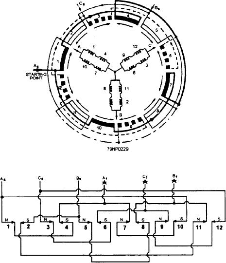
groups 1 and 4 are placed in parallel with pole-phase
Parallel-Wye winding
groups 10 and 7, resulting in an increase in the
current-carrying capacity. The voltage drop across that
To connect the machine for three-phase, four-pole,
phase remains the same without changing the number
parallel-wye operation, use the diagram shown in figure
7-62 with the same number of pole-phase groups and
of pole-phase groups.
the same assumed directions of current flow through the
groups as in the series-wye connection the pole-phase
Series-Delta Winding
groups of the three phases must be connected so that the
current flows through the various groups in the
The same machine connected for three-phase,
directions indicated to obtain alternate north and south
four-pole, series-delta operation is illustrated in figure
poles. Again, connect the battery, as previously
described, by connecting A, B, and C start phase to one
7-63. The same pole-phase group numbers are allotted
side of the battery; and A, B, and C finish phases to the
to the same phase windings, and the directions of current
other side. Again the 12 compass polarities should be
flow through the groups are the same as for the other
indicated in one revolution of the stator.
examples.
The only difference between the parallel-wye
Note the difference in the series-wye winding (fig.
winding (fig. 7-62) and the series-wye winding (fig.
7-60) and the series-delta winding (fig. 7-63). In the
7-60) is the four pole-phase groups, which were
series-delta winding, the three phases are connected so
originally in series in any one of the phases, but are now
that they form a delta, and the external connections are
split into two parallel paths of two pole-phase groups.
made at the three corners of the delta.
In phase A the same coil groups are used, but pole-phase
Figure 7-62.--Three-phase, four-pole, parallel-wye winding.
7-42

