consist of many turns of tine wire and series and
of round wire. These coils have only a few turns that
commutating field coils consist of fewer turns of heavy
are wound in a single turn per layer.
wire.
A series coil wound (with ribbon copper) on edge is
illustrated in figure 7-54. It is more difficult to bend the
Shunt Coils
copper ribbon, but it has an advantage in that both
terminal leads protrude on opposite sides of the coil.
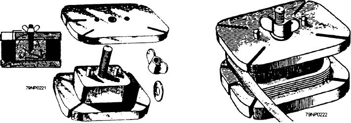
The equipment for rewinding shunt coils include a
Thus, the connections can be made very easily
lathe with a suitable faceplate, which can be turned at
compared to the strap-wound coils, which have one coil
any desired speed, and an adequate supply of the proper
end at the center and the other coil end at the outside of
size wire wound on a spool, which can be supported on
the. coil. The strap-wound construction requires leading
a shaft so that it is free to turn. Friction should be applied
the inside coil end over the turns of strap in the coil.
to the spool to provide tension on the wire. Secure a coil
form having the exact inside dimensions of the coil to
After the winding is completed, the coil is tested
electrically for continuity and shorted turns. It is then
the lathe or faceplate. The form for shaped field coils
prebaked, varnished, and tested for polarity, grounds,
can be made from a block of wood shaped exactly to the
opens, and shorts, as described previously, at each stage
required size and provided with flanged ends to hold the
in turn.
wire in place (fig. 7-53). One of the flanges should be
removable so that the finished coil can be taken from the
forming block.
Testing Field Coils
The wire is wound from the spool onto the forming
block for the required number of turns. The turns must
Before installing a new or repaired coil, test it for
be evenly spaced, one against the other, until the
winding procedure is completed. The turns of the
shorts, opens, and grounds, and determine its polarity.
completed coil are secured by tape, and the wire leading
The same precautions that were observed during
to the spool is cut, leaving sufficient length to make the
removal of the coil must be observed when installing it.
external connections. The completed coil must be
All of the shims originally removed from the pole piece
must be in position when it is replaced. With the coil
checked electrically for continuity and for shorted turns.
positioned in the machine, it should be temporarily
The coil is now prebaked and varnish treated as
connected to the other coils in the field circuit and a
specified in table 7-7. When varnish-treated, the
compass and battery again used to check its polarity.
finished field coil should withstand a high-potential test
For this test, connect the battery to the proper field leads,
of twice the rated excitation voltage plus 1,000 volts.
and check the polarity of all the coils with the compass
(fig. 7-55). Adjacent poles must be of oppsite polarity.
Series and Commutating Coils
If necessary, the polarity of the new coil can be reversed
by reversing the leads. When the polarity is correct, the
Series and commutating field coils are frequently
coil is connected, and the pole-piece bolts are tightened.
wound with strap (rectangular) or ribbon copper instead
Air gaps should be measured to ensure uniformity.
Figure 7-53.--Coil form for field coils.
Figure 7-54.--Edge wound series coil.
7-38

