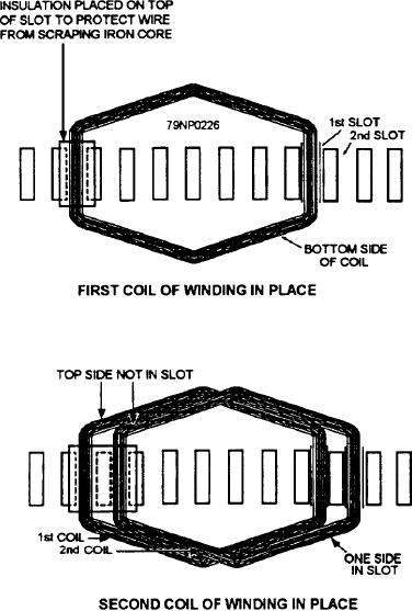
You rewind new coils for ac stator windings in the
coil and the inside lead of the next coil together.
same manner as for dc armatures, and you have to form
Connect the outside lead of the last coil with the inside
and shape them before you place them in the stator slots
lead of the next coil and bend the outside lead of this
(7-59).
coil away from the center. Repeat this procedure for
You now insert all the coils in the stator slots,
each of the pole-phase groups all around the stator. Do
insulate the ends, and drive the slot wedges in place (fig.
not solder the connection at this time.
7-59). Extending from each coil will be the start and
After twisting the ends together, check the
finish leads; these leads must be connected to form a
individual groups to determine that the proper number
series of coils called a pole-phase group.
of coils have been connected together in each
In arranging these coils into pole-phase groups, start
pole-phase group and that they have the proper
by bending (forming) the inside lead of the first coil
polarity. Then solder the twisted connections and cut
toward the center, and then twist the outside lead of that
off the ends so that the soldered stubs are about
three-quarters of an inch long. Insulate the stubs with
acrylic glass.
If the distance to the bearing brackets (frame of the
machine) is small, bend the insulated stubs so that they
may be laced to the end of the coils before the stator is
dipped. Now the stubs will not come in contact with the
frame when the stator is assembled.
In practice, the coils that comprise the pole-phase
groups are usually gang wound. Gang-wound coils
eliminate the need for stubbing because the coils are
wound with a continuous length of wire.
Series-Wye Winding
Before connecting the pole-phase groups together,
construct a diagram containing the pole-phase groups in
each phase and the number of poles for the particular
machine, as illustrated in figure 7-60. Pole-phase
groups for each phase are connected to produce alternate
north and south poles, and the direction of current flow
through each pole-phase group is indicated by the
arrows.
The As, Bs, and Cs phase leads (s stands for start)
are all connected to one polarity of a small battery; the
Af, Bf, and Cf phase leads (f stands for finish) are all
connected to the other polarity of the battery. If
connections are correct, a compass will give opposite
polarity as it is moved from one coil group to another.
Figure 7-59.--Placing coil sides in slots.
Note the changing polarity in figure 7-60.
7-40

