Wye Connection
armature (3) is rotated in the exciter field flux, voltage
is induced into the exciter armature windings. The
Rather than have six leads come out of the three-
exciter output commutator and brushes (4) connect the
phase ac generator, one of the leads from each phase is
exciter output directly to the ac generator field input slip
connected to form a common junction. The stator is
rings and brushes (5). Since slip rings, rather than a
then said to be wye, or star, connected. The common
commutator, are used to supply current through the ac
lead may or may not be brought out of the machine, If
generator field (6), current always flows in one direction
it is brought out, it is called the neutral. A simplified
through these windings. Thus, a fixed polarity magnetic
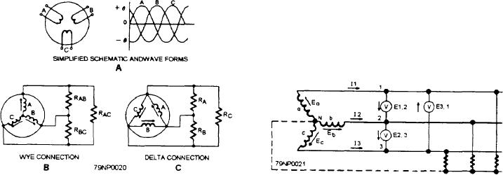
schematic (fig. 3-20, view B) shows a wye-connected
field is maintained at all times in the ac generator field
stator with the common lead not brought out. Each load
windings. When the ac generator field is rotated, its
is connected across two phases in series as follows:
magnetic flux is passed through and across the ac
generator armature windings (7). A voltage is induced
RAB is connected across phases A and B in series
into the stator windings by the relative motion of the
magnetic lines of flux cutting across and through the
WAC is connected across phases A and C in series
windings in the stator. The alternating voltage induced
RBC is connected across phases B and C in series
in the ac generator armature windings is connected
through fixed terminals to the ac load.
Thus, the voltage across each load is larger than the volt-
age across a single phase. In a wye-connected ac gen-
THREE-PHASE GENERATORS
erator, the three start ends of each single-phase winding
are connected together to a common neutral point, and
As the name implies, a three-phase ac generator has
the opposite, or finish, ends are connected to the line
three single-phase windings spaced so that the voltage
terminals, A, B, and C. These letters are always used to
induced in each winding is 120 out of phase with the
designate the three phases of a three-phase system or the
voltages in the other two windings. A schematic
three line wires to which the ac generator phases connect.
diagram of a three-phase stator showing all the coils
A three-phase, wye-connected ac generator
becomes complex, and it is difficult to see what is
supplying three separate loads is shown in figure 3-21.
actually happening. A simplified schematic diagram
When unbalanced loads are used, a neutral may be
showing all the windings of a single phase lumped
added as shown in the figure by the broken line between
together as one winding is shown in figure 3-20, view
the common neutral point and the loads. The neutral
A. The rotor is omitted for simplicity. The waveforms
wire serves as a common return circuit for all three
of voltage are shown to the right of the schematic. The
phases and maintains a voltage balance across the loads.
three voltages are 120 apart and are similar to the
No current flows in the neutral wire when the loads are
voltages that would be generated b y three, single-phase
balanced. This system is a three-phase, four-wire circuit
ac generators whose voltages are out of phase by angles
and is used to distribute three-phase power to
of 120. The three phases are independent of each other.
shore-based installations. The three-phase, four-wire
system is not generally used aboard ship, but it is widely
used in industry and in aircraft ac power systems.
Delta Connection
A three-phase stator may also be connected as
shown in figure 3-22. This type of connection is called
Figure 3-21.--Three-phase, ac generator showing neutral
Figure 3-20.--Three-phase ac generator.
connection.
3-16

