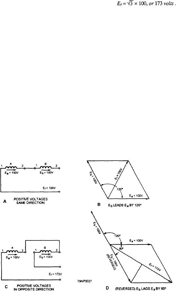
In equation form: If Ea and Eb are each 100 volts,
at figure 3-27.) For example, in view A, the positive
then
maximum voltage generated in coils A and B act in the
direction of the arrows, and B leads A by 120. This
arrangement may be obtained by assuming coils A and
B to be two armature windings located 120 apart. If
The value of Er may be derived as follows:
each voltage has an effective value of 100 volts, the total
voltage is Er = 100 volts, as shown by the polar vectors
1. Erect a perpendicular to Er divides the isosceles
in view B.
triangle into two equal right triangles.
If the connections of coil B are reversed (view C)
2. Each right triangle has a hypotenuse of 100 volts
with respect to their original connections, the two
and abase of 100 cos 30, or 86.6 volts.
voltages are in opposition. You can see this by tracing
3. The total length of Er is 2 x 86.6, or 173.2 volts.
the circuit in the direction of the arrow in coil A.
To construct the line voltage vectors E1,2, E2,3, and
1. The positive direction of the voltage in coil B is
E3,1, in figure 3-26, it is first necessary to trace a path
opposite to the direction of the trace
around the closed circuit that includes the line wires,
armature windings, and one of the three voltmeters. For
2. The positive direction of the voltage generated
example, in figure 3-21, consider the circuit that
in coil A is the same as that of the trace.
includes the upper and middle wires, the voltmeter
Therefore, the two voltages are in opposition.
connected across them, and the ac generator phases a
3. This effect is the same as though the positive
and b. The circuit trace is started at the center of the
maximum value of Eb were 60 out of phase
wye, proceeds through phase a of the ac generator, out
with that of Ea, and Eb acted in the same
line 1, down through the voltmeter from line 1 to line 2,
direction as& when the circuit trace was made
and through phase b of the ac generator back to the
(view D) to vector.
starting point. Voltage drops along line wires are
disregarded. The voltmeter indicates an effective value
4. Ea is accomplished by reversing the position of
equal to the vector sum of the effective value of voltage
Eb from that shown in view B, to the position
in phases a and b. This value is the line voltage, E1,2.
shown in view D, which completes the
According to Kirchhoff's law, the source voltage
parallelogram.
Figure 3-27.--Vector analysis of voltage in series aiding and opposing.
3-19

