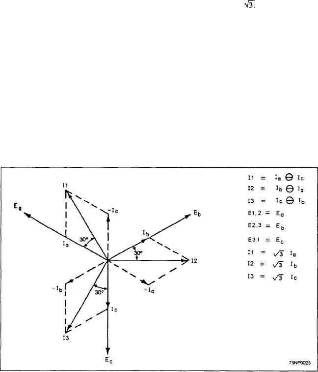
The line voltages (E1,2, E2,3, and E3,1) are the
between lines 1 and 2 equals the voltage drop across the
diagonals of three parallelograms whose sides are the
voltmeter connected to these lines.
phase voltages Ea, Eb, and Ec. From this vector
If the direction of the path traced through the
diagram, the following facts are observed:
generator is the same as that of the arrow, the sign of the
1. The line voltages are equal and 120 apart.
voltage is plus; if the direction of the trace is opposite to
the arrow, the sign of the voltage is minus. If the
2. The line currents are equal and 120 apart.
direction of the path traced through the voltmeter is the
3. The line currents are 30 out of phase with&
same as that of the arrow, the sign of the voltage is
line voltages when the power factor of the load
minus; if the direction of the trace is opposite to that of
is 100%.
the arrow, the sign of the voltage is plus.
4. The line voltage is the product of the phase
The following equations for voltage are based on
voltage and the
the preceding explanation:
Analysis of Delta-Connected Stators
E a + (-Eb) = E1,2, or E1,2 = Ea - Eb
E b + (-Ec) = E2,3, or E2,3 = Eb- Ec
by accompanying arrows in the generator phases in
E c + (Ea) = E3,1, or E3,1 = Ec - Ea
figure 3-22. These arrows point in the direction of the
The signs + and mean vector addition and vector
positive current and voltage of each phase. The three
subtraction, respective y. One vector is subtracted from
voltmeters connected across lines 1 and 2, 2 and 3, and
another by reversing the position of the vector to be
3 and 1, respectively, indicate effective values of line
subtraced through an angle of 180 and constructing a
and phase voltage. Line current 11 is supplied by phases
parallelogram, the sides of which are the reversed vector
a and c, which are connected to line 1. Line current is
and the other vector. The diagonal of the parallelogram
greater than phase current, but it is not twice as great
is the difference vector.
because the phase currents are not in phase with each
other. The relationship between line currents and phase
These equations are applied to the vector diagram
currents is shown in figure 3-28.
of figure 3-26. They are used, to derive the line voltages.
Figure 3-28.--Three-phase delta/connected system.
3-20

