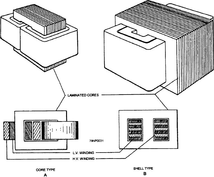
Figure 3-31.--Types transformer construction.
drop, half of each winding is placed on each leg of the
between magnetic particles as they are rotated through
core. The windings may be cylindrical in form and
each cycle of magnetization, are minimized by the use
of a special grade of heat-treated, grain-oriented,
placed one inside the other with the necessary
silicon-steel laminations.
insulation, as shown in figure 3-31, view A. The
low-voltage winding is placed with a large part of its
In the core type of transformer, copper windings
surface area next to the core, and the high-voltage
surround the laminated iron core. In the shell type of
transformer, an iron core surrounds the copper
winding is placed outside the low-voltage winding in
windings. Distribution transformers are generally of the
order to reduce the insulation requirements of the two
core type, whereas some of the largest power
windings. If the high-voltage winding were placed next
transformers are of the shell type.
to the core, two layers of high-voltage insulation would
If the windings of a core-type transformer were
be required, one next to the core and the other between
placed on separate legs of the core, a relatively large
the two windings.
amount of the flux produced by the primary winding
In another method, the windings are built up in thin,
would fail to link the secondary winding and a large
flat sections called pancake coils. These pancake coils
leakage flux would result. The effect of the leakage flux
are sandwiched together with the required insulation
would be to increase the leakage reactance drop, IXL, in
between them, as shown in figure 3-31, view B.
both windings. To reduce the leakage flux and reactance
3-25

