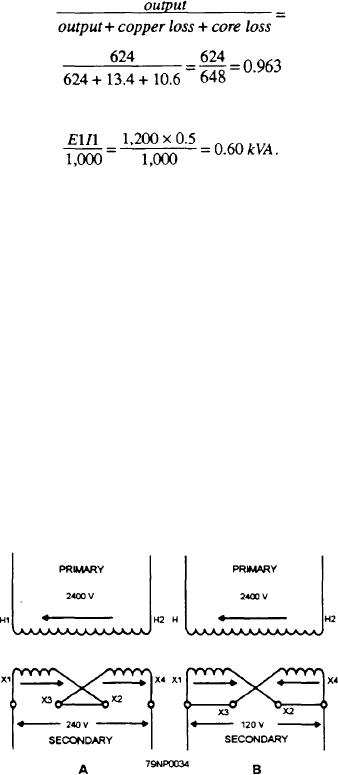
add. For example, if each secondary winding is rated at
(5)2 x 0.269= 6.725 watts, and the total copper loss is
120 volts and 100 amperes, the series-connection output
6.725 x 2 13.45 watts.
rating will be 240 volts at 100 amperes, or 24 kVA; the
The core losses, consisting of the hysteresis and
parallel-connection output rating will be 120volts at 200
eddy-current losses, caused by the alternating magnetic
amperes, or 24 kVA.
flux in the core are approximate] y constant from no load
In the series connection, care must be taken to
to full load with rated voltage applied to the primary.
connect the coils so their voltages add. The proper
In the transformer of figure 3-33, view A, if the core
arrangement is indicated in figure 3-34, view A. A trace
loss is 10.6 watts and the copper loss is 13.4 watts, the
made through the secondary circuits from X1 to X4 is
efficiency is
in the same direction as that of the arrows representing
the maximum positive voltages.
In the parallel connection, care must be taken to
connect the coils so their voltages are in opposition. The
correct connection is indicated in figure 3-34, view B.
The direction of a trace made through the secondary
windings from X1 to X2 to X4 to X3 and returning to
or 96.3 percent. The rating of the transformer is
X1 is the same as that of the arrow in the right-hand
winding. This condition indicates that the secondary
voltages have their positive maximum values in
directions opposite to each other in the closed circuit,
The efficiency of this transformer is relatively low
which is formed by paralleling the two secondary
because it is a small transformer and the losses are
windings. Thus, no circulating current will flow in these
disproportionately large.
windings on no load. If either winding were reversed,
a short-circuit current would flow in the secondary, and
CONNECTIONS
this would cause the primary to draw a short-circuit
current from the source. This action would, of course,
In this section we will discuss the differences
damage the transformer as well as the source.
encountered when dealing with transformer windings
connected for single- and three-phase operation.
Three-Phase Connections
Single-Phase Connections
Power may be supplied through three-phase circuits
containing transformers in which the primaries and
Single-phase distribution transformers usually have
secondaries are connected in various wye and delta
their windings divided into two or more sections, as
combinations. For example, three single-phase
shown in figure 3-34, view A. When the two secondary
transformers may supply three-phase power with four
windings are connected in series (fig. 3-34, view A),
possible combinations of their primaries and
their voltages add. When two secondary windings are
secondaries. These connections are
connected in parallel (fig. 3-34, view B), their currents
1. primaries in delta and secondaries in delta,
2. primaries in wye and secondaries in wye,
3. primaries in wye and secondaries in delta, and
4. primaries in delta and secondaries in wye.
Earlier under the heading Three-Phase Generators,
delta and wye connections were discussed. Also
discussed was the phase relationship between line and
phase voltages and that current is the same as in ac
If the primaries of three single-phase transformers
are properly connected (either in wye or delta) to a
Figure 3-34.--Single-phase transformer connections.
three-phase source, the secondaries may be connected
3-29

