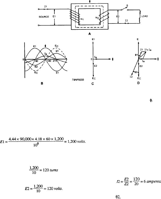
Figure 3-33.--Constant-potential transformer.
f is the frequency in hertz, and
produces the transformer core flux The flux produced
by 1. cuts the primary winding, N1, and induces a
N is the number of complete turns in the winding
counter voltage, Ec, 180 out of phase with E1 in this
For example, if the maximum flux density is 90,000
winding. The voltage, E2, induced in the secondary
lines per square inch, the cross-sectional area of the core
winding is in phase with the induced (counter) voltage,
is 4.18 square inches, the frequency is 60 Hz, and the
E., in the primary winding, and both lag the exciting
number of turns in the high-voltage winding is 1,200,
current and flux, whose variations produce them, by an
the voltage rating of this winding is
angle of 90. These relations are shown in vector form
in figure 3-33, view C. The values are only approximate
and are not drawn exactly to scale.
When a load is connected to the secondary by
If the primary-to-secondary turns ratio of this
closing switch S (fig. 3-33, view A), the secondary
transformer is 10 to 1, the number of turns in the
current, I2, depends upon the magnitude of the
low-voltage winding will be
secondary voltage, E2, and the load impedance, Z. For
example, if E2 is equal to 120 volts and the load
impedance is 20 ohms, the secondary current will be
and the voltage induced in the secondary will be
If the secondary power factor is 86.6 percent, the
phase angle,
between secondary current and voltage
For a more in-depth explanation of voltage and
will be the angle whose cosine is 0.866, or 30.
current relations, refer to NEETS, Module 2,
Introduction to Alternating Current and Transformers,
The secondary load current flowing through the
NAVEDTRA 172-02-00-88, Topic 5, Transformers.
secondary turns comprises a load component of
magnetomotive force, which, according to Lenz's law,
The waveforms of the ideal transformer with no
is in such a direction as to oppose the flux that is
load are shown in figure 3-33, view B. When E1 is
producing it. This opposition tends to reduce the
applied to the primary winding, N1, with the switch, S,
transformer flux a slight amount. The reduction in flux
open, the resulting current, Ia, is small and lags E1 by
is accompanied by a reduction in the counter voltage
almost 90 because the circuit is highly inductive. This
induced in the primary winding of the transformer.
no-load current is called the exciting, or magnetizing,
Because the internal impedance of the primary winding
current because it supplies the magnetomotive force that
3-27

