where, E1 and E2 are the induced voltages in the
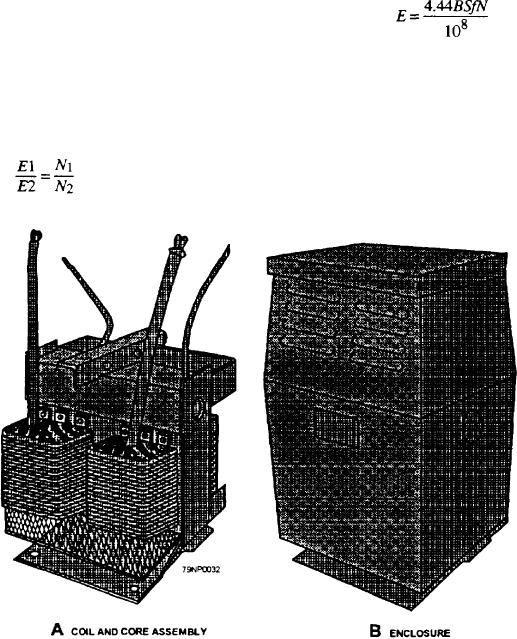
The complete core and coil assembly (fig. 3-32,
primary and secondary windings, and
view A) is placed in a steel tank. In some transformers,
the complete assembly is immersed in a special mineral
N1 and N2 are the number of turns in the
oil to provide a means of insulation and cooling, while
primary and secondary windings.
in other transformers they are mounted in dripproof
In ordinary transformers, the induced primary
enclosures, as shown in figure 3-32, view B.
voltage is almost equal to the applied primary
Transformers are built in both single-phase and
voltage; hence, the applied primary voltage and the
polyphase units. A three-phase transformer consists of
secondary induced voltage are approximately
separate insulated windings for the different phases,
proportional to the respective number of turns in the two
which are wound on a three-legged core capable of
windings.
establishing three magnetic fluxes displaced 120 in
A constant-potential, single-phase transformer is
time phase.
represented by the schematic diagram in figure 3-33,
VOLTAGE AND CURRENT RELATIONSHIPS
view A. For simplicity, the primary winding is shown
as being on one leg of the core and the secondary
The operation of the transformer is based on the
winding on the other leg. The equation for the voltage
principle that electrical energy can be transferred ef-
induced in one winding of the transformer is
ficiently by mutual induction from one winding to another.
When the primary winding is energiaed from an ac source,
an alternating magnetic flux is established in the
transformer core. This flux links the turns of both primary
and secondary, thereby inducing voltages in them.
where:
Because the same flux cuts both windings, the same
E is the rms voltage
voltage is induced in each turn of both windings. Hence,
the total induced voltage in each winding is proportional
B is the maximum value of the magnetic flux
to the number of turns in that winding; that is,
density in lines per square inch in the core
is the cross-sectional area of the core in square
S
inches
Figure 3-32.--Single-phase transformer.
3-26

