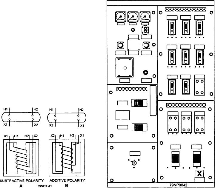
When the H1 and X1 leads are brought out on
the primaries in wye because the line voltage is 73
opposite corners of the transformer (fig. 3-41, view B),
percent higher than the phase voltage, and the line
the polarity is additive. If the H1 and X2 leads are
current is accordingly less. Thus, the line losses are
connected and a reduced voltage is applied across the
reduced, and the efficiency of transmission is improved.
H1 and H2 leads, the resultant voltage across the H2 and
X1 leads in the series circuit formed by this connection
POLARITY MARKING OF POWER
will equal the sum of the voltages of the two windings.
TRANSFORMERS
The voltage of the low-voltage winding aids the voltage
of the high-voltage winding and adds to it, hence the
term additive polarity.
It is essential that all transformer windings be
properly connected and that you have a basic
Polarity markings do not indicate the internal
understanding of the coding and the marking of
voltage stress in the windings. They are useful only in
transformer leads.
making external connections between transformers.
The leads of large power transformers, such as those
400-HERTZ POWER DISTRIBUTION
used for lighting and public utilities, are marked with
numbers, letters, or a combination of both. This type of
In addition to the 60-hertz power supplied by the
marking is shown in figure 3-41. Terminals for the
ship's service generators, ships also have 400-hertz
high-voltage windings are marked H1, H2, H3, and so
forth. The increasing numerical subscript designates an
increasing voltage, denoting a higher voltage between
H1 and H3 than the voltage between H1 and H2.
The secondary terminals are marked X1, X2, X3,
and so forth. There are two types of markings that may
be employed on the secondaries. When the H1 and X1
leads are brought out on the same side of the transformer
(fig. 3-41, view A), the polarity is called subtractive.
The reason this arrangement is called subtractive is as
follows: If the H1 and X1 leads are connected and a
reduced voltage is applied across the H1 and H2 leads,
the resultant voltage that appears across the H2 and X2
leads in the series circuit formed by this connection will
equal the difference in the voltages of the two windings.
The voltage of the low-voltage winding opposes that of
the high-voltage winding and subtracts from it, hence
the term subtractive polarity.
Figure 3-42.--400-hertz switchboard.
Figure 3-41.--Polarity markings for large transformers.
3-34

