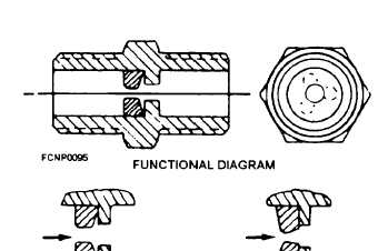
Figure 1-18.—Equipment flow regulator.
individual cabinets and components is shown in figure
1-18. It maintains a constant flow of distilled water with
limited changes in the input pressure. At the minimum
water flow, the total amount of water is passed through
the device. As the flow of water increases to the flow
regulators maximum limit, the water flow is restricted
by the insert’s movement, which causes the hole size to
decrease. In this way, the flow of water is regulated.
The amount of water that the flow regulator will pass is
usually stamped on the side of the regulator. This is
because the external dimensions are usually the same
for differently rated regulators.
The nominal flow rate of the equipment-flow
regulator can be from one-half to more than 12 gallons
per minute.
It is normally used with a pressure-
regulating valve. You should be aware that this type of
regulator can deteriorate over time. The insert can
become distorted and cause a reduction in the flow of
water. With a drill index set, you can use the back of a
drill bit to measure the hole size and compare it to a
known good constant-flow regulator or the equipment
manual. Do not drill out the insert to restore it to the
proper size, because it will become distorted. Its
distorted shape would prevent the insert from regulating
the distilled water flow.
The pressure-regulating valve (fig. 1-19) is used to
regulate a major section of the coolings system; whereas,
the flow regulator is normally used to regulate an
individual feeder line to an individual component or
cabinet. The pressure-regulating valve usually has a
pressure-relief valve downstream from it to protect the
equipment from being over pressurized. Should a
failure occur in the pressure regulating valve, the
pressure-relief valve would keep the water pressure at a
safe level to prevent equipment damage.
The operation of a typical pressure-regulating valve
is as follows: When a drop in downstream (outlet)
pressure occurs, the pressure in the diaphragm chamber
is lowered concurrently. The downstream side of the
valve is connected to the diaphragm chamber through a
narrow opening along the periphery of the piston. The
Figure 1-19.—Pressure regulator.
1-16


