outlet and the bypass and then proportions the two flows
to obtain the desired temperature. The three-way
regulating valve’s range of operation is within
degrees of the setting on the valve.
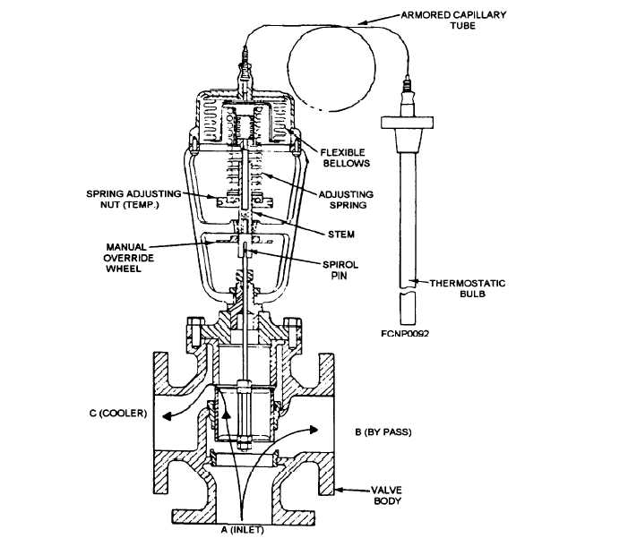
Refer to figure 1-15 for the following description of
the operation of the three-way regulating valve.
The bulb contains a volatile liquid that vaporizes
and expands when heated. The generated pressure in
the bulb is a function of the temperature around it. This
pressure is transmitted through capillary tubing to the
flexible bellows, which are loaded by the spring. Both
bellows and spring rest on the end of the valve stem.
Expansion or contraction of the bellows causes
movement of the stem and the piston in the valve body.
The flow of the liquid entering the valve at port A is
proportioned between ports B and C in the proper ratio
to maintain the mixed flow temperature at the valve’s
set point. Total flow through the valve remains
constant. Movement of the bellows is opposed by the
spring, which is provided with a means to adjust the
operating temperature by the spring-tension adjustment
wheel. A drop in temperature at the thermostatic bulb
reduces the pressure in the thermostatic assembly,
causing it to exert less force, resulting in an upward
movement of the stem because of the force of the spring.
As the stem is connected to the piston, the piston also
moves upward, enabling more liquid to pass from the
bottom inlet through the right outlet (bypass) side and,
at the same time, restricting flow through the left outlet
(heat exchanger) side. A rise in temperature at the
thermostatic bulb results in a reversed effect.
Figure 1-15.—Three-way temperature regulating valve.
1-13


