In the event that the magnetic pickup fails (or before
initial start-up), capacitor C1 becomes discharged,
allowing fail-safe transistor Q4 to turn off.
When this condition occurs, the fail-safe supply
voltage reverse biases zener diode VR2. This clamps
the speed sensor output voltage at approximately -2.4
volts. This simulates a high engine speed to the
summing point to decrease the engine fuel supply to
minimum.
Load Sensor
In the load sensor (fig. 9-20) A2 monitors the
voltage levels from the external potential and current
transformers. From these input signals, the load sensor
computes the total kW load on the generator and
produces a dc voltage proportionate to the load
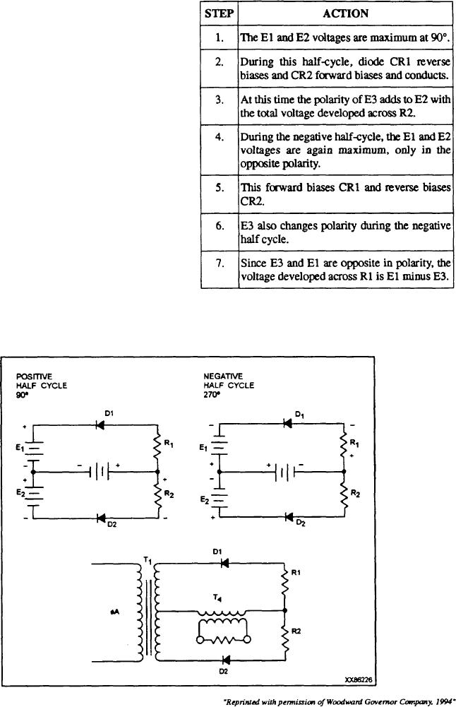
Figure 9-21 shows one phase of the load sensor and
the equivalent voltage circuits for 90 and 270
transition through the sine wave. As shown, current
input transformer T4 can be represented by battery E3,
During periods of no load, voltage at E3 is 0 V
the value and polarity of which is dependent on load and
and the voltage developed across R1 and R2 is equal to
sine wave transition. During the positive half cycle, the
the voltage at E1 and E2.
following actions occur:
Figure 9.21--Equivalent single-phase circuit.
9-29

