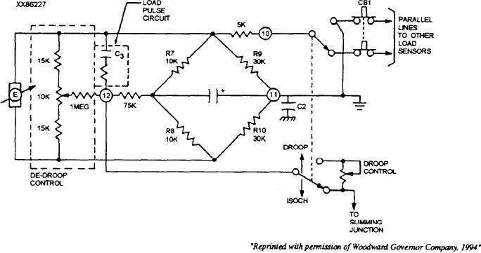
the load on the generator increases, the load voltage
During no load there is no current signal and
from the bridge circuit (terminal 12) increases
consequently no voltage is developed across the current
negatively. This negative voltage is applied to the
transformer. This results in a 0 volt load signal since the
DROOP potentiometer which sets the amount of series
three phases cancel each other out.
resistance. In this mode the negative load voltage biases
LOAD GAIN control A2Rl (fig. 9-20) is connected
the speed setting signal downward as the load increases.
in parallel with the voltage adder circuit. The output of
PARALLEL UNIT ISOCHRONOUS.-- The load
the variable LOAD GAIN control (represented as
sensor provides proportional load sharing when two or
variable voltage source E in fig. 9-22) is applied across
more generating units are parallel in the isochronous
the bridge circuit. This then is the load control signal
mode. In this mode each load sensor compares the load
for this particular prime mover.
of its generating unit with the load of other units
A dc-droop circuit is connected across the output of
producing power and either increases or decreases fuel
the LOAD GAIN potentiometer and applies a portion of
to the engine to maintain its proportional share of the
this load voltage as bias to the output of the load sensor.
load.
This counteracts any inherent droop in the overall
system.
When the mode switches are set for isochronous
operation for a parallel engine combination, their load
An optional load pulse circuit (fig. 9-22)
sensor bridge circuits are connected together through
differentiates any sudden load voltage output from the
the paralleling lines (see fig. 9-23). In this mode of
LOAD GAIN control caused by a sudden load change.
operation, the bridge circuits are balanced with terminal
The load puke provides a lead signal to the amplifier
11 as a common reference point.
summing point and minimizes the off speed and
recovery time associated with large and sudden load
When paralleling two or more units, each engine
changes.
takes on its proportional share of the load by equalizing
the load voltages across the bridge network.
SINGLE UNIT ISOCHRONOUS.-- During
single-unit isochronous operation, the bridge circuit is
As an example, assume that two units are paralleled
balanced; thus the load sensor output is 0 volt. Under
The first unit has a 100-kW capacity and the second has
this condition the speed sensor maintains engine speed
50 kW. Unit 1 is operating at 75 percent capacity and
unit 2 is at rated speed with no load. The load sensor for
SINGLE UNIT DROOP.-- Setting the external
both units is calibrated for 9 volts at full load. However,
mode switch to DROOP connects AIR11 to dc common.
E1 for unit 1 is 6.75 volts (9 volts x 0.75) and E2 for unit
This unbalances the bridge network, producing a
2 is 0 volt (9 volts x 0.00), caused by the different load
Figure 9-22.-Basic load sensor, single-unit configuration.
9-30

