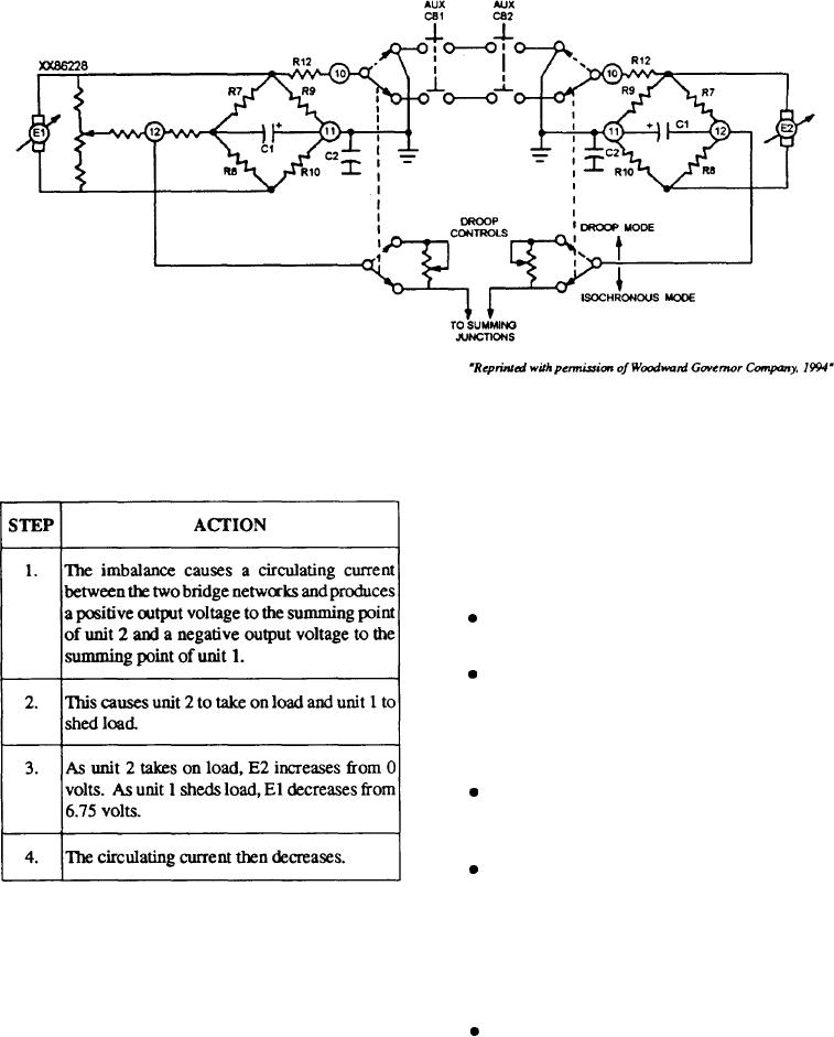
Figure 9-23.--Basic load sensor, parallel unit configuration.
MAINTENANCE
conditions. This condition exists at the moment of
paralleling, causing an electrical imbalance between the
Maintenance for the 2301 electric governor should
two load sensor bridge networks.
be conducted on a regular basis. The first step in the
procedure is to look for any obvious physical defects.
Missing, loose, or damaged electrical or mechanical
connections often result in more serious maintenance
problems if not corrected. Other maintenance
suggestions are as follows:
Transformers. Inspect all transformers for loose
or broken terminals. Check all mounting hardware.
Controls. Inspect all controls for loose mounting,
damaged wipers, or contacts and smoothness of
operation. Do not disturb the setting of a
screwdriver-adjusted control unless it is suspected of
being faulty.
Terminal blocks. Inspect all terminal blocks for
cracks, chips, or loose mounting hardware. Check all
wiring terminals for loose wires or lugs.
Printed circuit boards. Inspect printed circuit
boards for secure mounting and proper location in the
unit. It is not advisable to remove circuit boards for the
This continues until E1 equals E2 (4.5 volts) and
sole purpose of inspecting them for physical damage.
both generators share the load proportionally. Unit 1 is
Components mounted on printed circuit boards should
producing 50 kW, and unit 2 is producing 25 kW for a
be checked for secure mounting and poor electrical
total power of 75 kW.
connections.
The load sensors are only active during unequal
Wiring. Inspect all wiring for frayed or burned
had changes when a circulating current develops
leads. Insure that insulating sleeves are in place. Check
between the bridge networks. During an unequal
for loose or broken lacing in harnesses.
change, the bridge networks are electrical y unbalanced,
and the action is always toward proportional load
When power is secured, dust and foreign matter can
sharing.
be removed by brushing with a clean dry brush. Large
9-31

