Input Voltage Distribution
Speed Setting Reference Voltage
Since the speed setting input voltage determines the
The 2301 electric control operates with either a
speed of the prime mover, a stable reference voltage is
24-volt dc supply or a 32-volt dc supply. The source of
necessary for stable speed control. Zener diode
this supply can be either a battery or a regulated dc
A1A1VR1 provides a stable 6.6-volt dc at TB1 terminal
power supply.
21 (fig. 9-15) for the speed-setting control.
Resistors R4 and R5 (see block schematic diagram
Amplifier
fig. 9-15) are current-limiting resistors for zener voltage
regulators A1VR1 and A1VR2 (see amplifier schematic
fig. 9-16). When you are using a 24-volt dc supply, this
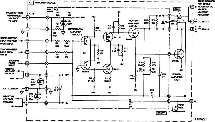
Input signals from the various input and control
operating voltage is applied to TB1 terminals 12 (+) and
circuits (fig. 9-16) are algebraically added together at
13 (-) (fig. 9-15). When you are using a 32-volt dc
the summing point input to the amplifiler (A1TB1
supply, operating voltage is applied to TB1 terminals 25
terminal 5). The steady-state condition of the closed
loop (sensors, amplifier, actuator, fuel flow, prime
(+) and 13 (-). Resistor R6 drops the +32-volt to
+24-volt dc before being applied to current-limiting
mover speed, sensors) is a value approaching null
resistor R5.
voltage at the summing point input to the amplifier.
The speed-setting input voltage (positive) at A1TB1
Protection diode CR1, mounted on the panel, is in
terminal 10 is algebraically added to the speed sensor
series with the negative voltage supply lead (common
voltage (negative) at the summing point (A1TB1
to both the 24-volt and 32-volt dc supplies). The diode
terminal 5). A resultant positive voltage causes input
protects the circuitry by reverse biasing if the input
transistor A1A1Q1 to turn on and conduct. This causes
voltage polarity should ever be reversed.
the differential amplifier to become unbalanced. The
Voltage regulators A1VR1 and A1VR2 regulate the
Q1A emitter potential decreases conduction through
24-volt dc to +9 and -9 volt dc with respect to center tap
Q1B. The Q1B collector potential decreases
common (A1TB1 terminal 6). This +9 and -9 volt dc is
conduction through Q2. Collector potential from Q1A
the regulated supply voltage for the 2301 electric control
forward biases A1A1Q3, causing increased conduction
system.
through Q3.
Figure 9-16.--Amplifier schematic.
9-24

