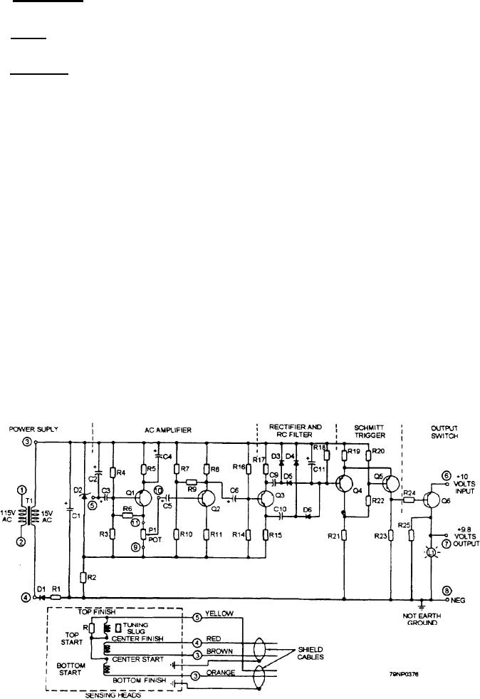
The power supply (fig. 5-28), consisting of the
Schmitt-Trigger
115/15 volt transformer, D1, D2, C1, R1, and R2.
The Schmitt-trigger, consisting of Q4 and Q5,
The voltage across D2 used to bias the succeeding
presents a voltage across R23, which is used to bias the
amplifier stages.
output switch transistor Q6 to its ON a OFF state.
The Zener diode (D2) has a breakdown voltage of
Output Switch
12 volts, which protects the following stages from
overvoltage.
The proximity switch supplies only the switching
power. Proximity limit switch terminals 6 and 8 connect
Sensing Heads
to a 10-Volt, dc static logic power source. This power
source is supplied at terminals 7 and 8 and the proximity
The sensing heads (fig. 5-28) consist of two coils
light is lit when Q6 switches to the ON state.
connected in series opposition, which, when energized
When the target is in the sensing zone, the sensing
by mutual inductance from a third coil, are balanced by
head has an output that is amplified rectified, and
means of a tuning slug. A resistor, connected in parallel
filtered, switching the output of the Schmitt-trigger off.
with the top sensing coil, is used for positioning the
This turns the output switch Q6 (fig. 5-28) to its ON
sensing heads. An output voltage is produced by the
position. Therefore, when the target is in the sensing
sensing head when an elevator cam target enters the
zone, there is an output and the status light L1 is on.
field, resulting in an output to terminals 3 and 5.
MAINTENANCE
AC Amplifier
As with all electrical and electronic equipment,
The input to the ac amplifier is supplied by the
preventive maintenance must be performed on a routine
sensing head at terminals 3 and 5 (fig. 5-28). The
basis and according to the PMS and the manufacturer's
sensing head signal is amplified by three cascaded
instruction manuals. Good housekeeping practices and
amplifier stages consisting of Q1, Q2, and Q3 with
routine adjustments play an important part in the
suitable biasing networks. The amplifier output is fed
maintenance of elevator controllers.
through a rectifier consisting of D3, D4, D5, and D6.
Pay special attention to the proximity switches. Do
This signal is filtered by the RC network of C11 and R18
to drive the following Schmitt-trigger.
Figure 5-28.--Schematic diagram of a proximity limit switch.
5-46

