
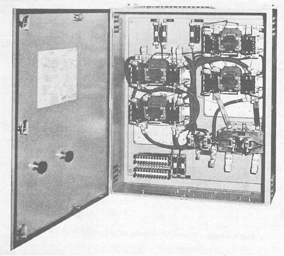
Figure 5-27.--AC magnetic reversing controller for a two-speed, two-winding motor for a cargo elevator.
sensing zone to create a signal. The signal strength
by the static logic control system. The voltage output is
depends primarily on the distance between the face of
+10 volts when the cam target on the elevator car is
the sensing head and the target.
moved in front of the sensing head mounted on the
elevator shaft. The voltage output is zero when the cam
Operation of a proximity limit switch maybe best
is moved away from the sensing head (deactuated). The
explained by examining the following basic circuits and
metallic elevator target to be sensed must enter the
components:
5-45