
The three-phase, 400-volt, 60-hertz motor drives
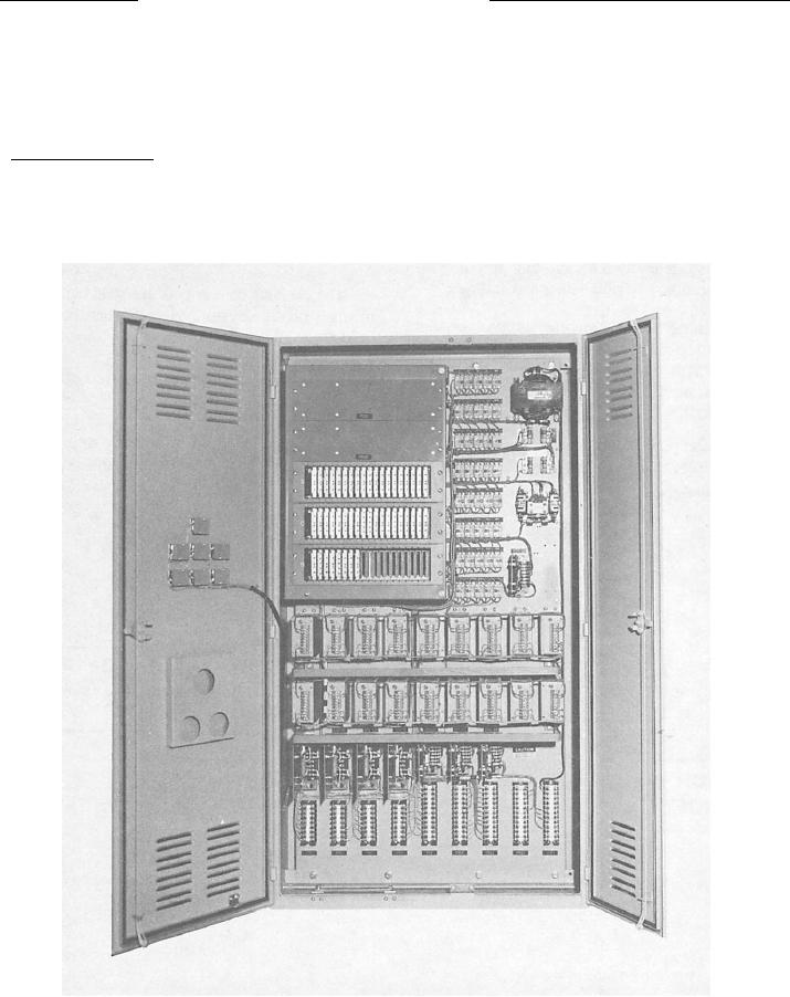
The static logic panel is a solid-state, low-power
system that performs functions normally associated.
the elevator
with limit switches, relays, and contactors (fig. 5-26).
The logic modules consist of proximity switches, signal
PROXIMITY LIMIT SWITCHES
converters, retentive memories, reset memories, shift
registers, duo-delay timers, and pulses with
Proximity limit switches (electronic limit switches)
appropriate logic elements and circuitry.
are used extensively to control elevator movement.
Basically, the proximity switch consists of a remotely
The motor controller (fig. 5-27) energizes
located sensing head and a logic module that amplifies
appropriate contractors to control the speed and
the sensing head voltage to a positive 10-volt level used
rotation of the motor.
Figure 5-26.--A static logic panel at the sixth level for a cargo elevator.
5-44