
As already mentioned, additional protection is
ELECTROHYDRAULIC ELEVATOR
provided through a system of series-connected
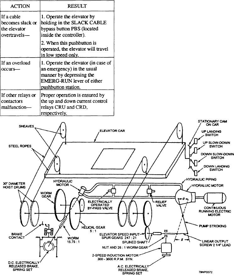
The electrohydraulic elevators use hoisting cables
interlocks in the control circuit. These interlocks consist
and drums in much the same manner as the electric
of door, slack cable, and overtravel switches. The
elevator. In this system, however, the cable drums are
following table lists some of the means of elevator
driven through reduction gears by a hydraulic motor.
operation during malfunctions:
Raising, lowering, or speed changes are accomplished
by varying the stroke of the variable delivery hydraulic
pump through differential gearing. Figure 5-24 shows
a typical arrangement scheme for operation of the
electrohydraulic bomb elevators.
The elevators use a follow-up type control system
so that the pump is put on stroke by a pilot motor and
the stroke is taken off by the motion of the platform
working on the follow-up control.
On some elevators, the pilot motor is started by
depressing an operating pushbutton. The pilot motor
moves the pump control piston to the ON-STROKE
position, and the elevator accelerates to full speed.
Upon approaching the selected level, a platform
mounted cam trips a slow-down switch that
de-energizes the pilot motor. Movement of the platform
then returns the stroke of the pump to the NEUTRAL
position. On reaching the selected level, a stop switch
de-energizes the brake solenoid to set the brake and stop
Figure 5-24.--Bomb elevator power plant and control scheme.
5-42