Figure 3-41.—Probe coupling in a rectangular waveguide.
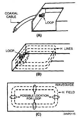
Figure 3-42.—Loop coupling in a rectangular
waveguide.
For the most efficient coupling to the waveguide,
the loop is inserted at one of several points where the
magnetic field will be of greatest strength. Four of
those points are shown in figure 3-42, view C.
When less efficient coupling is desired, you can
rotate or move the loop until it encircles a smaller
number of H lines. When the diameter of the loop
is increased, its power-handling capability also
increases.
The bandwidth can be increased by
increasing the size of the wire used to make the loop.
When a loop is introduced into a waveguide in
which an H field is present, a current is induced in
the loop.
When this condition exists, energy is
removed from the waveguide.
Slots or apertures are sometimes used when very
loose (inefficient) coupling is desired, as shown in
figure 3-43. In this method energy enters through
a small slot in the waveguide and the E field expands
into the waveguide. The E lines expand first across
the slot and then across the interior of the waveguide.
3-19


