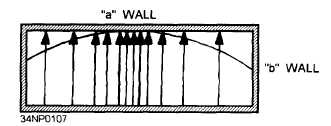
Figure 3-34.—Half-sine E field distribution.
The half-sine field is only one of many field
configurations, or modes, that can exist in a rectangular
waveguide.
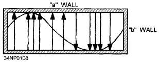
A full-sine field can also exist in a
rectangular waveguide because, as shown in figure
3-35, the field is zero at the “b” walls.
Figure 3-35.—Full-sine E field distribution.
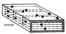
The magnetic field in a rectangular waveguide is
in the form of closed loops parallel to the surface of
the conductors. The strength of the magnetic field
is proportional to the electric field. Figure 3-36
illustrates the magnetic field pattern associated with
a half-sine electric field distribution. The magnitude
of the magnetic field varies in a sine-wave pattern
down the center of the waveguide in “time phase” with
the electric field. TIME PHASE means that the peak
H lines and peak E lines occur at the same instant in
time, although not necessarily at the same point along
the length of the waveguide.
The dominant mode is the most efficient mode.
Waveguides are normally designed so that only the
dominant mode will be used. To operate in the
dominant mode, a waveguide must have an “a” (wide)
dimension of at least one half-wavelength of the
frequency to be propagated. The “a” dimension of
the waveguide must be kept near the minimum
allowable value to ensure that only the dominant mode
will exist. In practice, this dimension is usually 0.7
wavelength.
Figure 3-36.—Magnetic field caused by a half-sine
E field.
Of the possible modes of operation available for
a given waveguide, the dominant mode has the lowest
cutoff frequency.
The high-frequency limit of a
rectangular waveguide is a frequency at which its “a”
dimension becomes large enough to allow operation
in a mode higher than that for which the waveguide
has been designed.
Circular waveguides are used in specific areas of
radar and communications systems, such as rotating
joints used at the mechanical point where the antennas
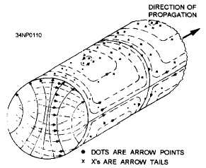
rotate. Figure 3-37 illustrates the dominant mode of
a circular waveguide.
The cutoff wavelength of a
circular guide is 1.71 times the diameter of the
waveguide. Since the “a” dimension of a rectangular
waveguide is approximately one half-wavelength at
the cutoff frequency, the diameter of an equivalent
circular waveguide must be 2/1.71, or approximately
Figure 3-37.—Dominant mode in a circular
waveguide.
3-16


