. Real-time clock —Allows real-time clock to be
updated internally or externally
Consult your technical manuals for exact
operations used in the different computer operating
modes.
MAN/MACHINE INTERFACE FUNCTIONS
The man/machine interface is used to perform a
variety of general functions. These functions include,
but are not limited, to the following:
l
o
l
l
l
l
l
l
l
Configure the computer/processor system
Apply power
Enter data and display data
Execute internal diagnostics
Execute bootstrap
Initiate operational programs
Execute auto restart operations
Execute diagnostics
Patch or revise software
Not every man/machine interface function applies
to every type of computer; therefore, we look at the
three general types of computers (microcomputers,
minicomputers, and mainframes) and give an overview
of the man/machine interfaces used for each particular
type as it applies to you. We do not address
microprocessors as such. We consider them as
replaceable or repairable components of the larger
device. We also do not discuss peripheral devices used
for system control and configuration operations. The
following discussion covers only those man/machine
interface devices considered as components or
assemblies of the particular type of computer. With all
types of computers, consult the appropriate
documentation for your system to ensure proper
operation.
This last statement cannot be over
emphasized.
Microcomputers
The man/machine interfaces used with the
microcomputers you maintain will be system oriented.
Let’s take a look at the options available to you for
microcomputers.
CONFIGURE THE PROCESSOR.—
Microcomputer systems are designed to be flexible in
their configuration.
You can easily modify most
desktop systems to incorporate additional disk units
(hard or floppy), expanded memory, other components,
as well as specific operator requirements. The
ROM-based firmware that the system uses for booting
the operating system as well as other system software
must be configured for the current system
interconnection scheme.
Three methods are commonly used to inform the
processor of the system configuration. They are DIP
switches, jumpers, and battery protected storage of
configuration data.
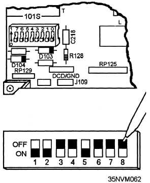
DIP Switches.—Dual-inline package (DIP)
switches are made to be instilled into integrated circuit
sockets or board connections. Each switch in the
package (fig. 8-18) normally indicates one of two
conditions by its ON/OFF status. The board mounted
DIP switches are designed so you can manually position
them during component installation, removal, or initial
system configuration to inform the processor of the
availability of the particular components as well as the
requirements of the system operators. They affect such
operations as video display (color and resolution) and
port(s) selections. Individual switches or combinations
of two or three switches are used to specify a variety of
configuration options.
Jumpers. —In some units, jumpers are used to
make additional configuration changes. Jumpers (fig.
8-19) can be likened to dual-inline package (DIP)
Figure 8-18.—DIP switches.
8-16


