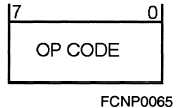
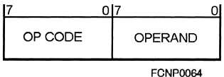
Figure 8-9.—Illustration of instruction word format V.
Extended Operand Addressing
Extended addressing. is used when an address of a
memory location is too large to fit in one word. For
example, on a computer with an 8-bit word (1 byte),
only memory locations with addresses within the range
of 0 through 255 can be addressed in 1 byte. To enable
the computer to address memory locations with larger
addresses, two bytes can be interpreted as one address.
See figure 8-11.
Immediate Operand Addressing
When the immediate format is used, the operand
itself is contained in the instruction. In this instruction
format, the destination is a general-purpose register
defined by the destination register code (fields or
designators) located in the instruction. Figure 8-12 is
an example of immediate addressing.
Implicit (Implied) Operand Addressing
In implicit (implied) operand addressing, the
operand location is implied by the op (function) code of
the instruction (fig. 8-13). For example, the op code
CLA could mean “clear the accumulator.” No address
needs to be specified because the op code contains all
the information needed.
Indexed Operand Addressing
In the indexed mode, the operand address must be
generated when the instruction is being prepared for
execution. This is done by adding the address given in
the instruction to a value contained in a specified
register. The register to be used is specified along with
the operand address in the instruction. See figure 8-14.
In this example, the parentheses are used to tell that the
index mode is needed. The CPU will add the operand
whose address is ADDR1 + the value in register 1, R1,
Figure 8-10.—Example of direct addressing format.
Figure 8-11.—Example of extended addressing format.
Figure 8-12.—Example of immediate addressing format.
Figure 8-13.—Example of implicit (implied) addressing
format.
Figure 8-14.—Example of indexed addressing.
8-11


