on the processor input or output bus. The processor
input and output bus allows the microprocessor to
communicate directly with the disk drives and the data
bus control unit. Two holding registers, the processor
input bus holding register and the processor output bus
holding register, allow the microprocessor to receive
data from and send data over the data bus.
The 16-bit bidirectional data bus is used primarily
to transfer read/write data, external function
commands, interrupt codes, and status codes between
the CDS channel interface, buffer memory, the disk
control logic, and the microprocessor bus holding
registers. The data bus control unit, under control of the
microprocessor, directs the flow of data over the data
bus.
Microprocessor
The microprocessor controls the overall operation
of the controller circuitry and therefore the overall
operation of the magnetic disk set. All communications
between the microprocessor and other elements of the
controller pass over the processor input or output buses.
The actions of the microprocessor are governed by
8,192 microinstructions stored as firmware in read-only
memory (ROM) or micromemory. Address logic in the
microprocessor determines which instructions will be
read out of micromemory and executed. Under normal
operation, a microinstruction is read out of
micromemory and executed every 250 nanoseconds.
The address of the next microinstruction to be executed
may be conditional, depending on the presence or
absence of a condition, signal, or interrupt, or the next
instruction to be executed may be unconditionally
specified by the current microinstruction.
A large variety of hardware conditions is sensed by
the microprocessor logic in determining the
microinstruction to be executed. Much of the
information used by the microprocessor is contained in
a look-up table. The look-up table is a 2,048 address
ROM containing the following information:
micromemory jump addresses, data masks, constants,
and code conversion tables for the status/maintenance
panel function/message codes.
Additional random access memory (RAM) is
provided by 256 16-bit words of RAM called the FILE.
The file is used for temporary storage of diagnostic test
parameters and other variable quantities during
operation of the magnetic disk set.
Buffer Memory
Buffer memory is used to prevent the loss of data
when reading from or writing onto disk. The CDS
channel interface and the disk drives may operate at
different speeds. A direct transfer from the channel
interface to the drive could result in the loss of data. The
4,096 16-bit addresses of buffer memory, expandable to
8,192 addresses, are used as a temporary storage area
for blocks of data when performing read or write
operations.
During a write operation, data is transferred from
the CDS channel interface over the data bus to the
random access buffer memory and stored in blocks.
The blocks of data are then transferred a word at a time
over the 16-bit data bus to the disk control logic and
written on disk. The opposite applies in a read
operation. Data is read from disk and transferred into
buffer memory and then transferred to the channel
interface for input to the computer. Read and write
operations do not occur at the same time.
Controller to Disk Drive Interface
The controller to disk drive interface provides for
control of up to four disk drives, one internal to the disk
unit and up to three drives installed in memory units.
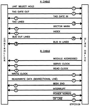
As shown in figure 10-16, there are two separate
Figure 10-16.—A cable and B cable interfaces and signals.
10-18


