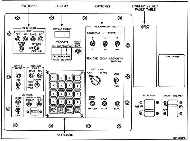
Figure 8-26.—Power up switches located on a maintenance control panel.
an ac power switch is activated to apply ac power to the
have two panels, others one panel. When two are used,
computer. The circuit breaker will kick OFF in the
event the computer power supplies draw excessive
current.
The ac switch allows ac voltage to be fed to the
blower fans and dc power supply. Indicators, usually
one for PRIMARY and one for LOGIC, show the
presence of stable dc power when illuminated. Some
minicomputers will have a 4-digit time meter to record
the accumulated hours that logic power has been
applied.
Some minicomputers are equipped with a battle
short switch to allow the computer to run even when
the temperature exceeds the normal allowable operating
temperature established by the manufacturer. An
audible alarm and/or indicators can also be used to
indicate excessive temperature.
USE CONTROLS, DATA ENTRY, AND DATA
DISPLAY.— The controls, data entry, and displays
used on minicomputers vary. Some minicomputers
one panel is used for control and the other for
maintenance. When one panel is used, the control and
maintenance functions are located on the same panel.
Refer again to figure 8-26. The panels on some
minicomputers can be likened to the keyboard of a
microcomputer; they deal primarily with the operating
system and software programs. But with some
minicomputers, you have more options. They include
controls and indicators that deal with power and
temperature. These two conditions were included in the
apply power man/machine interface.
In addition to a number of control switches and
indicator lamps, some minicomputers use a keyboard
for data entry and numeric displays to show the contents
of registers or display status. This is also illustrated in
figure 8-26.
EXECUTE INTERNAL DIAGNOSTICS.—
Internal diagnostics are built-in tests (BITs). Firmware
and testing features are designed into the logic modules
8-21


