The program for the MPC is stored in ROM. The
sequence of instructions obtained from the ROM, by the
MPC, determines what, when, and how events will be
done in the MTU. All computation, such as parity
checks or operational decoding of external function
words, is performed by the MPC.
Two data buses, the source bus and the des-
tination bus, are used for data transfer to and from the
MPC. The MPC receives data via the source bus and
transmits data via the destination bus. The source and
destination of data are determined by ROM program
instructions.
The MPC performs the following functions within
the control unit:
Interprets external function commands received
from the external computer(s)
Converts computer data to tape frames as
specified by external function words (write
operation)
Converts tape frames to computer data as
specified by external function words (read
operation)
Forms status words for the external com-
puter(s)
Initiates start/stop delays
Determines frame lateral parity bit, and checks
for lateral parity errors
Forms longitudinal parity check fumes, and
checks for longitudinal parity errors
l
l
l
l
l
l
Peforms comparisons for search operations
Checks frame count for lost frames
Detects end of records
Detects input (write) and output (read) timing
errors
Performs cyclic redundancy checks
Selects MTT
The remaining elements of the control unit provide
the communications links between the MPC and the
external computer(s), and the MPC and the MTTs.
Additional functions performed by the control unit
circuitry include the following:
l
l
l
l
l
l
l
Read/write signal amplification (to/from MTT
read/write heads)
Deskewing (frame alignment)
Density selection, control, and timing
Time delays (start/stop)
Dual computer operation control (duplex)
Computer electrical interface matching
Offline channel interface and timing
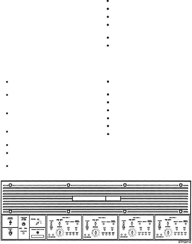
MTU SYSTEM CONTROL PANEL.— The
system control panel, as shown in figure 9-17, contains
the controls and indicators for primary power and tape
transport manual control. Controls and indicators for
the controller include the main power circuit breaker,
mode select, overtemp alarm, and overtemp alarm
bypass. Controls and indicators for each tape
Figure 9-17.—An MTU system control panel.
9-14


