program. The information about these tracks can be
transmitted to other units over the Link-11 net. The
computer sends data to the data terminal set using 24-
bit data words. The computer also receives
information about remote tracks from other units in
the net and displays these tracks through the display
system.
Shipboard Gridlock System
Gridlock is the matching of track positions held
by other ships with the tracks held by your own ship.
Gridlock is a procedure for determining data
registration correction by comparing remote tracks
received from a designated reference unit to local
data. Ideally, tracks received from remote units that
are also displayed by onboard sensors should be
transparent, that is, in the exact same position on the
CRT. If the gridlock system does not provide
correlation between local and remote tracks, the
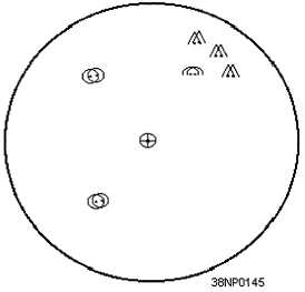
remote tracks may be painted twice and overlap each
other, as shown in figure 4-3.
Figure 4-3.—Tracks out of gridlock.
Failure to maintain gridlock may be the result of
inaccurate positioning data from a ship’s sensor, from
the Ship’s Inertial Navigation Systems (SINS), or from
the ship’s gyro. Failure to maintain gridlock may also
be the result of an inaccurate operator entry.
The SGS computer performs continuous
automatic gridlock calculations. In the event of an
SGS computer failure, the flow of Link-11 data to the
CDS computer is interrupted. To restore Link-11 data
flow, all SGS installations have switches installed that
allow the technician to bypass the SGS computer until
the fault is corrected.
Link-11 Security Device
A standard model security device, such as the
TSEC/KG-40, commonly referred to as the KG-40, is
used with the Link-11 system. When the DTS is
transmitting data, the KG-40 receives parallel data
from the CDS computer, encrypts the data, and sends
it to the DTS. When the participating unit (PU) is
receiving data, encrypted data is received from the
DTS, decrypted, and sent to the CDS computer.
Because of the specialized training and security
requirements of cryptographic equipment, we will not
cover the internal operation and controls of the
security device.
Data Terminal Set (DTS)
The data terminal set (DTS) is the heart of the
Link-11
system.
The
DTS
is
the
system
modulator/demodulator (MODEM). the CDS
computer sends 24 bits of data to the DTS via the
SGS computer and the encryption device. The DTS
adds six bits of data for error detection and correction.
These six bits are called hamming bits. The 30 bits
of data are phase shift modulated into 15 audio tones.
These 15 data tones and a Doppler correction tone are
combined into a composite audio signal, which is sent
to either the UHF or HF radio for transmission.
The DTS receives the composite audio signal from
the radio and separates the 15 data tones and the
Doppler correction tone. The 15 data tones are
demodulated into 30 data bits. The six hamming bits
are checked for errors and the 24 data bits are sent to
the CDS computer via the encryption device and the
SGS computer.
Link-11 Communications Switchboard
The communications switchboard provides for
manual switching of the data terminal set and
individual HF and UHF radios. The communications
switchboard provides system flexibility and casualty
4-3


