10-18) with the value of coil settings, installation
is used to connect sections of cable. In some cases,
information, and a log section showing the details of
splicing is used instead of through boxes.
the action taken on the ship's degaussing system.
A wire diagram of the connections in the box is
The folder is prepared by degaussing range
pasted on the inside of the cover and coated with varnish
personnel when the ship's degaussing system is initially
or shellac. The wiring diagram for connection boxes
calibrated.
should (1) designate the conductors that may be
reversed without reversing the other loops, (2) indicate
the arrangement of parallel circuits so equal changes can
PREVENTIVE MAINTENANCE
be made in all parallel circuits when such changes are
Preventive maintenance is extensive for automatic
required, and (3) show the spare conductors. Spare
degaussing systems. The degaussing switchboards and
conductors should be secured to connection terminals in
the connection boxes and should not form a closed or
remote panels require frequent cleaning and inspection
as they are sensitive to heat and dirt. The removal of
continuous circuit. All conductors in a connection box
dirt and dust from automatic degaussing control
should be 1 1/2 times the length required to reach the
farthest terminal within the box. Connection boxes
equipment allows the natural flow of air around the
should also have drain plugs accessible to provide for
components for heat dissipation. Use of a vacuum
periodic removal of accumulated moisture from the
cleaner or bellows is a safe way to remove dust or dirt.
boxes.
Do not use compressed air.
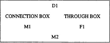
Connection and through boxes have
Check the connection or through boxes for
moisture. Drain plugs are installed in the bottom of
IDENTIFICATION PLATES that include degaussing
box numbers (such as D1 and D2), connection box
connection or through boxes to help you accomplish
and/or through boxes as applicable, and coil and loop
your inspection. When you notice moisture in a box
designations (such as Ml, M2, and F12).
during your inspection, leave it open to dry out. At the
same time, check the box cover gasket for deterioration,
and replace it if necessary.
When performing any preventive or corrective
maintenance on AUTODEG, observe standard
electrical safety precautions.
For additional information on degaussing systems,
refer to the Naval Ships' Technical Manual, chapters
300 and 475, and the manufacturers' instruction books.
This sample identified the No. 1 degaussing box serving
as a connection box for the M1 and M2 loops and as a
SUMMARY
through box for the F1 loop.
In this chapter, we have discussed the degaussing
systems installed aboard ships of the Navy. After
DEGAUSSING FOLDER
studying the information, you should have a better
The degaussing folder is an official ship's log. It
understanding of the earth's magnetic field, ship's
contains information on the magnetic treatment of the
magnetic fields, degaussing coils, ranging procedures,
ship, instructions for operating the shipboard
operation of various types of systems, and cable
degaussing system, degaussing charts (figs. 10-17 and
markings for degaussing installations.
10-19

