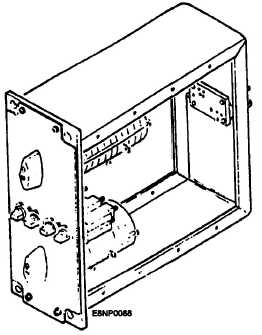
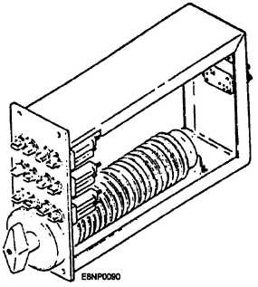
Figure 5-22.-Snap switch panel assembly.
flashing system indicators when a warning or
emergency condition occurs. Motor-driven dual-cam
and three-cam activated switches open and close
control or status signal circuits to provide the
flashing effect on indicator lamps.
Snap Switch Panel Assembly
The snap switch panel assembly (fig. 5-22)
provides manual control of switchboard power buses.
An individual panel mat contains either one or two
snap switches.
The snap switch (fig. 5-23) is a device that opens
or closes a circuit with a quick motion. Rotary snap
Figure 5-23.-Snap switch.
switches are used extensively in the distribution
sections of switchboards to connect the shipboard
power supplies to the various switchboard power
buses.
Manually Operated JR Switch Panel
Assembly
The manually operated JR switch panel assembly
(fig. 5-24) provides manual switching and action
cutout (ACO) functions. The manually operated JR
switch panel assembly uses either a 2JR or 4JR
switch. Both switch types are similar in construction
and differ only in the electrical application because of
switching action. A JR switch as shown in figure 5-25
is made up of a variable number of wafer-like
sections, As the switch is manually positioned, one or
more moveable contacts are positioned to each switch
position on the wafer. The contacts may connect
(bridge) two or more contacts on each wafer
effectively opening or closing circuit paths as
required to configure the system for normal or
alternate operation.
Remotely Operated JR Switch Panel
Assembly
The remotely operated JR switch panel (fig. 5-26)
provides remote and manual control of signal routing
and ACO switching. The automatic junction rotary
(AJR) switches used in these assemblies are driven by
a motor and gear train servo system. The automatic
switches allow control of switching functions from
remote stations. Analog switchboards used with
combat
Figure 5-24.-Manually operated JR switch panel
assembly.
5-14


