CREW LIVING SPACE, FRAMES XX - XX
FIRST PLATFORM
LIGHTING PANEL 4-108-2
2S-4L-(4-103-2)
If a panel contains two or more sets of buses and
each set is supplied by a separate feeder, the number of
each feeder will be indicated on the identification plate.
Distribution panels have circuit information plates
next to the handle of each circuit breaker or switch.
These plates contain the following information in the
order listed:
1. The circuit number.
2. The name of the apparatus or circuit controlled.
3. The location of the apparatus or space served.
4. The circuit breaker element or fuse rating.
Vital circuits are shown by red markers attached to
circuit information plates. Information plates for circuit
breakers supplying circle W and circle Z class
ventilation systems contain, in addition to the red
marker, the class designation of the ventilation system
supplied. Information plates without markings are
provided for spare circuit breakers mounted in
distribution panels. Panel switches controlling circuits
that are de-energized during darkened ship operations
are marked DARKENED SHIP. The ON and OFF
position of these switches are marked LIGHT SHIP and
DARKENED SHIP, respectively.
Circuit information plates are provided inside fuse
boxes (next to each set of the fuses). They show the
circuit controlled, the phases or polarity, and the ampere
rating of the fuse.
PHASE SEQUENCE
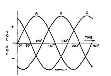
The phase sequence in naval ships is ABC; that is,
the maximum positive voltages on the three phases are
reached in the order A, B, and C (fig. 3-3). Phase
sequence determines the direction of rotation of
three-phase motors. Therefore, a reversal of the phase
sequence could cause damage to loads, especially
pumps, driven by three-phase motors. The phase
sequence of the power supply throughout a ship is
always ABC (regardless of whether power is supplied
from any of the switchboards or from the shore power
connection) to ensure that three-phase, ac motors will
always run in the correct direction.
Figure 3-3.-Sine curve for three-phase circuit.
Phase identification is denoted by the letters A, B,
and C in a three-phase system. Switchboard and
distribution panel bus bars and terminals on the back of
switchboards are marked to identify the phase with the
appropriate letters, A, B, or C. The standard
arrangement of phases in power and lighting
switchboards, distribution panels, feeder distribution
boxes, feeder junction boxes, and feeder connection
boxes is in the order A, B, and C from top to bottom,
front to back or right to left when facing the front of the
switchboard, panel, or box, and left to right when facing
the rear of the switchboard, panel, or box.
BUS TRANSFER SWITCHES
Bus transfer equipment is used to provide two
sources of power to equipment that is vital to the ship.
This vital equipment is that equipment needed to operate
safely or could cause the ship to become disabled if it
becomes de-energized.
Depending upon the application, the transfer from
one source to another may be done manually, by a
manual bus transfer switch, or automatically by an
automatic bus transfer switch.
MANUAL BUS TRANSFER (MBT)
SWITCHES
When normal power to vital equipment is lost,
power must be restored as soon as possible to ensure the
safety of the ship. MBTs maybe used to switch from
normal to alternate or emergency power for those loads
that draw a large starting current or for which some
condition must be met before energizing. A good
example of this would be HF radio equipment, if power
would be automatically reapplied after a sudden loss,
major damage would occur to the transmitter.
3-3


