Figure 3-9.-Disconnect links.
The switchboards shown in figures 3-5,3-6, and 3-7
are representative of the found on most gas-turbine
powered ships today. These switchboards use sheet
steel panels or enclosures from which only the meters
and the operating handles protrude to the front.
Distribution of the generated power begins with the
switchboard. These switchboards can be connected
together through bus tie circuit breakers to form a
continuous loop. This allows any two of the three gas
turbine generator sets (GTGS’s) to supply the demand
for power, while the third can be set up to start
automatically in the event of a power loss. (See figure
3-8.)
Each of the switchboard units of a group are
connected together through disconnect links (fig. 3-9).
By removing the links between any two of the
switchboards, repairs or replacement of parts may be
accomplished without interfering with the operation of
the other units.
GROUND DETECTOR CIRCUITS
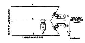
A set of three ground detector lamps (fig. 3-10) is
connected through transformers to the main bus of each
ship’s service switchgear group. It provides you with a
means to check for grounds on any phase of the
three-phase system.
To check for a ground, turn switch S on and observe
the brilliancy of the three lights. If the lights are equally
bright, all lights are receiving the same voltage, and no
ground exists. If lamp A is dark and lamps B and C are
bright, phase A is grounded. In this case, the primary of
the transformer in phase A is shunted to ground, and
lamp A receives no voltage. Similarly, if lamp B is dark
and lamps A and C are bright a ground exists on phase
B. If lamp C is dark and lamps A and B are bright, a
ground exists on phase C.
Figure 3-10.-An ac ground detector lamp circuit.
3-7


