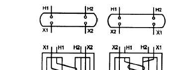
marking is shown in figure 3-17. Terminals for the
high-voltage windings are marked H1, H2, H3, and so
forth. The increasing numerical subscript designates an
increasing voltage, denoting a higher voltage between
H1 and H3 than the voltage between H1 and H2.
The secondary terminals are marked X1, X2, X3,
and so forth Two types of markings maybe employed
on the secondaries. When the H1 and X1 leads are
brought out on the same side of the transformer (fig.
3-17, view A), the polarity is called subtractive. The
reason this arrangement is called subtractive is if & H1
and X1 leads are connected and a reduced voltage is
applied across the H1 and H2 leads, the resultant voltage
that appears across the H2 and X2 leads in the series
circuit formed by this connection will equal the
difference in the voltages of the two windings. The
voltage of the low-voltage winding opposes the
high-voltage winding and subtracts from it; hence the
term, subtractive polarity.
When the H 1 and X1 leads are brought out on
opposite corners of the transformer (fig. 3-17, view B),
the polarity is additive. If the H1 and X2 leads are
connected and a reduced voltage is applied across the
H1 and H2 leads, the resultant voltage across the H2 and
X1 leads in the series circuit formed by this connection
will equal the sum of the voltages of the two windings.
The voltage of the low-voltage winding aids the voltage
of the high-voltage winding and adds to it, hence the
term, additive polarity.
Polarity markings do not indicate the internal
voltage stress in the windings. They are useful; only in
making external connections between transformers.
F’igure 3-17.-Polarity markings for large tramsformers: A.
Subtractive polarity; B. Additive polarity.
400-HERTZ POWER
DISTRIBUTION
In addition to the 60-Hz power supplied by the
ship’s service generators, ships also have 400-HZ
systems. On some ships 400-Hz power is generated by
motor-generator sets and distributed via special
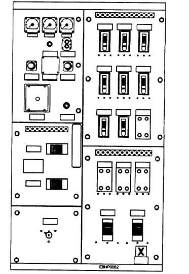
frequency switchboards (fig. 3-18) to the various
400-Hz equipment.
These motor generators supply power to ship’s
service special frequency switchboards. Figure 3-19 is
a simplified line diagram of the 400-Hz ship’s service
bus tie interconnections on an older ship. The circuits
being fed from the 400-HZ ship’s service switchboards
are deleted from the figure for simplicity.
Newer ships get their supply of 400-Hz power
through the use of 60/400-HZ static converters. The
400-Hz system consists of four MBT’s supplying 60-Hz
power to four 60/400-Hz static frequency converters
Figure 3-18.-400-Hz switchboard.
3-12


