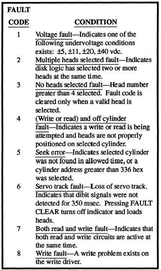
technician. The single-digit FAULT indicator displays
one of eight fault codes as defined in table 10-8.
Table 10-8.—Status/Maintenance Panel Fault Codes
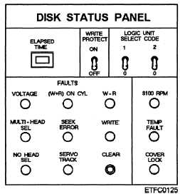
Figure 10-13.—A disk status panel (memory unit only).
Disk Status Panel
The disk status panel, shown in figure 10-13, is
found on the memory unit (MU). It performs the same
functions as a status/maintenance panel with the
exception of the FUNCTION/MESSAGE and FAULT
readout. As the memory units do not have a controller,
the readout is replaced by a number of FAULT
indicators and a CLEAR push button. The faults
indicated are the same as the eight fault readout
conditions listed in table 10-8. The CLEAR pushbutton
does not clear the fault condition, it clears the indicators
only if the fault condition causing the indication has
been corrected.
Some disk memory sets have a FORMAT WRITE
PROTECT switch. It is designed to protect the disk
packs from being inadvertently formatted when the
pack contains data that would be lost. When the switch
is in the ON position, disk pack testing commands from
the CDS computer and formatting commands from the
CDS computer or the STATUS/MAINTENANCE
panel are rejected. If the disk memory set in your sys-
tem has this switch, it should be left in the ON position
except when a disk pack is being tested or formatted.
Power Supply Panel
The power supply panel shown in figure 10-14
contains switches for MAIN POWER and for
advancing the FAULT DISPLAY (FAULT ADVANCE)
in the event of multiple power supply faults. A
two-digit FAULT DISPLAY displays a two-digit code
indicating POWER ON status or fault condition.
DISK MEMORY SET CONTROLLER
The controller has five functional areas as shown in
figure 10-15. They are as follows:
. Microprocessor
l Buffer memory
l Controller to disk drive interface
. Data bus control unit (DBCU)
. CDS channel interface
Controller Intercommunications
The functional areas of the controller are interfaced
by a bus arrangement. Two buses are used: (1) the
processor input and output bus and (2) the data bus. All
data and commands to/from the microprocessor move
10-16