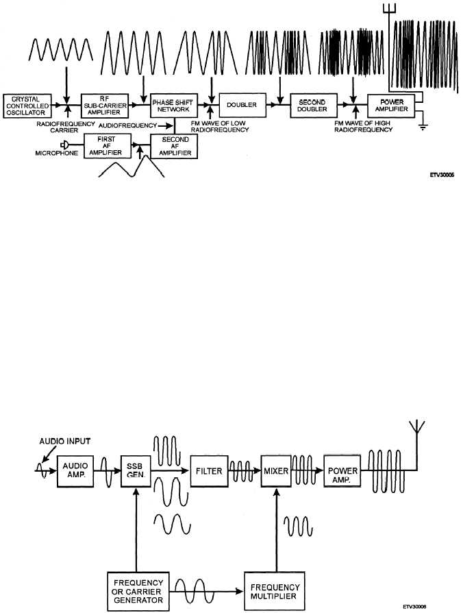
Figure 1-5.—FM transmitter block diagram.
We can make ssb even more efficient by removing
one of the sidebands. By filtering out one of the side-
bands before it reaches the power amplifier, all the
transmitter energy is concentrated into one side-
band instead of being split between the carrier and
two sidebands. This allows us to use less power for
transmission. Other advantages are a narrower re-
ceiver bandpass and the ability to place more signals in
a small portion of the frequency spectrum. Figure 1-6
is a block diagram of a ssb transmitter.
RECEIVERS
Earlier you were introduced to one link in a com-
munications system, the transmitter. All that is needed
to complete the system is a radio receiver. A receiver
processes modulated signals and delivers, as an output,
a reproduction of the original intelligence. The signal
can then be applied to a reproducing device, such as a
loudspeaker or a teletypewriter.
RECEIVER FUNCTIONS
To be useful, a receiver must perform certain basic
functions. These functions are reception, selection, de-
tection, and reproduction.
Reception
Reception occurs when a transmitted electromag-
netic wave passes through the receiver antenna and in-
duces a voltage in the antenna.
Figure 1-6.—SSB transmitter block diagram.
1-7


