problem with most transceivers, some do have provi-
sions for separate transmit and receive operations, al-
lowing them to overcome the problem.
ANCILLARY EQUIPMENT
Now that we have looked at the basic components
of a communications system, let’s identify some of the
ancillary equipment required to make a transmitter and
receiver useful.
HANDSET
A handset converts acoustical (sound) energy into
electrical energy, which is used to modulate a transmit-
ter. It also converts electrical energy into acoustical en-
ergy for the reproduction of the received signal.
To key a transmitter, the push-to-talk button is de-
pressed, closing the dc keying circuit, which places the
transmitter on the air. The handset is normally con-
nected to a radio set control but can be used locally at
the transmitter. Using the “local” option is a good way
to determine whether a problem exists in the transmit-
ter or remote equipment.
RADIO SET CONTROL
The radio set control provides the capability to
control certain transmitter functions and the receiver
output from a remote location. Some control units con-
tain circuits for turning the transmitter on and off,
voice modulating the transmission, keying when using
CW, controlling receiver output, and muting the re-
ceiver when transmitting.
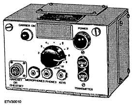
A representative radio set control unit is shown in
figure 1-10. As many as four of these units maybe par-
alleled to a single transmitter/receiver group to provide
additional operating positions. This setup is often
found aboard ship when a transmitter or receiver is
controlled from various locations like the bridge or
combat information center.
TRANSMITTER TRANSFER
SWITCHBOARD
The transmitter transfer switchboard allows the re-
mote control station functions and signals to be trans-
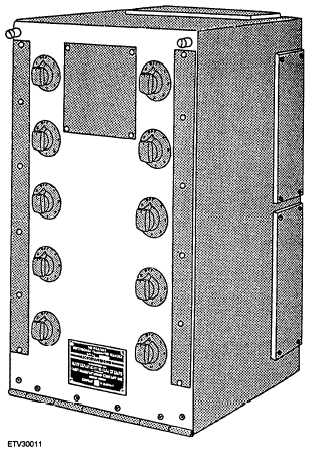
ferred selectively to the transmitters. Figure 1-11
shows a transfer switchboard that allows the functions
and controls of anyone, or all, of 10 remote control sta-
tion functions and signals to be transferred selectively
to any one of six transmitters. Each knob corresponds
Figure 1-10.—Radio set control
Figure 1-11.—Transmitter Transfer Switchboard (SB-
988/SRT).
to a remote control station and has 8 operating posi-
tions. Positions 1 through 6 correspond to attached
transmitters. The seventh position (X) allows for
switching of the transmitters to another switchboard.
The eighth position (OFF) removes the remote from
the system.
1-12


